
LMCN078HV Engineering Manual
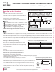

Wiring / Cable Connections
Power Wiring
Wired
Controller
Cable
Control Box Cover
Control Box
Cover Screws
Connecting the Power Wiring and
Communications Cable
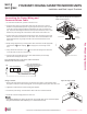
1. To access the terminal block, open the control box cover.
2. Insert the power wiring / communications cable from the outdoor unit or branch
distribution unit (Multi F MAX systems only) through the sides of the indoor unit and
control box. Pass the wiring through the designated access holes to prevent dam-
age. To prevent electromagnetic interference and product malfunction, leave a space
between the power wiring and communications cable outside of the indoor unit.
3. Connect each wire to its appropriate terminal on the indoor unit control board. Verify
that the color and terminal numbers from the outdoor unit or branch distribution unit
(Multi F MAX systems only) wiring match the color and terminal numbers on the
indoor unit.
4. Neatly arrange power wiring / communications cable and secure with the appropriate
cable restraint. When clamping, do not apply force to the wiring connec-
tions.
5. Firmly reattach the control box cover. Do not catch the wiring in the electric box
cover and make sure the cover firmly closes.
6. Fill in any gaps around the wiring access holes with sealant to prevent foreign
particles from entering the indoor unit.
Figure 203:Power Wiring and Communications
Cable Connection Access.
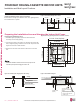
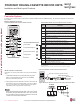
Figure 204:Simplied View of Indoor Unit to Outdoor Unit / Branch
Distribution Unit Terminal Connections.
Installation and Best Layout Practices
FOUR-WAY CEILING CASSETTE INDOOR UNITS
Ceiling cassette 4-way _ 19
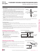
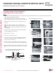
Rubber Stopper
Cable
Conduit
Screws
Conduit Bracket
Using a Conduit
1. Remove the rubber stopper on the indoor unit. Pass the power wiring / communications cable
through the conduit, the conduit mounting plate, and to / through the control panel of the indoor unit.
2. Tighten the conduit and the conduit mounting plate together.
3. Connect the power wiring / communications cable to the indoor unit terminal block.
4. Screw the conduit mounting plate to the indoor unit.
Figure 205:Using a Conduit.
If the distance between the outdoor unit and indoor unit is greater than 131 feet, connect the power
wiring and communications cable separately (i.e., a conduit cannot be used).
Indoor Unit Terminal Block
GND
Outdoor Unit Terminal Block or
Branch Distribution Unit Terminal Block
(Multi F MAX Systems Only)
GND
GRN / YLW
BR
BL
RD
3 or S
32(L2)1(L1)
CEILING-CASSETTE | 155
Four-Way Ceiling-Cassette
Due to our policy of continuous product innovation, some specications may change without notication.
©LG Electronics U.S.A., Inc., Englewood Cliffs, NJ. All rights reserved. “LG” is a registered trademark of LG Corp.
MULTI
F
MAX
MULTI
F