
Multi F Engineering Manual


STD. WALL-MOUNTED | 51
Standard Wall-Mounted
'XHWRRXUSROLF\RIFRQWLQXRXVSURGXFWLQQRYDWLRQVRPHVSHFL¿FDWLRQVPD\FKDQJHZLWKRXWQRWL¿FDWLRQ
©/*(OHFWURQLFV86$,QF(QJOHZRRG&OLIIV1-$OOULJKWVUHVHUYHG³/*´LVDUHJLVWHUHGWUDGHPDUNRI/*&RUS
MULTI
F
MAX
MULTI
F
Dimensions
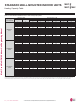
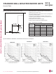
STANDARD WALL-MOUNTED INDOOR UNITS
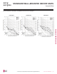
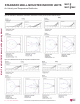
)LJXUH LMN079HVT, LSN090HSV5, LSN120HSV5, and LMN159HVT Dimensions.
Unit : Inch (mm)
30-3/16 (767)
32-15/16 (837)
3-5/8 (92)
2-3/8 (60)
2-5/16
(59)
12-1/8 (308)
7-7/16 (189)
32-15/16 (837)
1-1/2 (38)
Approx. 8-19/32 (218) to liquid pipe
Approx. 11-11/32 (288) to gas pipe
1-27/32(47)
5-3/16 (132)
In Case of Left Side Piping
Unit Outline
Connecting Gas/Liquid Pipe
12-1/8 (308)
2-7/32(56)
11/32 (9)
5/16 (8)
2 (51)
Air Intake
Air Outlet
Bottom
[28-5/32 (715)]
Air Outlet Hole
* If airflow direction control is available,
Cooling Heating
Up & Down Left & Right
Air Outlet Hole
Air Intake Hole
[5-29/32 (150)]
Air Intake Hole
Rear
Rear
Right
Left
55°
15°
15°
85°
45°
55°
32-15/16 (837)
2-15/32
(63)
12-1/16 (306)
3-21/32 (93)
10-11/32 (263)
5-31/32 (152)
3-27/32 (98)
5-9/32 (134)
12-1/8 (308)
3-11/16 (94)
7-5/8 (194)
Unit Outline
Fixing the Installation Plate, Drilling Hole
29/32 (23)
Ø2-9/16 (65)
2-7/16 ( 61.5)
1-7/16 (33.5)
1-9/32 (32.7)
2-13/32
(61)
5-31/32 (152)
2-7/32 (56)
2 (51)
2-7/32 (56)
Ø2-9/16 (65)
29/32 (23)
2-15/32 (63)
2-17/32 (64)
5-19/32 (142)
7-27/32 (199)
7-27/32 (199)
1/4 (6) x 1/8 (3)
1/8 (3) x 1/4 (6)
5/8 (15.3)
1-1/4 (31)
1-3/32 (50.2)
1-1/16 (26.2)
Refrigerant,
Drain Pipe
and Cable
Routing
Knock Out
Hole
Refrigerant,
Drain Pipe
and Cable
Routing
Knock Out
Hole
Terminal Block for
Power Supply and
Communication
Refrigerant, Drain
Pipe and Cable
Routing Knock Out Hole
Drain Hose
Connection
Display & Remote
Controller Signal
Receiver
Decoration Cover
Installation Plate