
Multi F Engineering Manual
'XHWRRXUSROLF\RIFRQWLQXRXVSURGXFWLQQRYDWLRQVRPHVSHFL¿FDWLRQVPD\FKDQJHZLWKRXWQRWL¿FDWLRQ
©/*(OHFWURQLFV86$,QF(QJOHZRRG&OLIIV1-$OOULJKWVUHVHUYHG³/*´LVDUHJLVWHUHGWUDGHPDUNRI/*&RUS
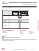
66 | STD. WALL-MOUNTED
Multi F and Multi F MAX Indoor Unit Engineering Manual
MULTI
F
MAX
MULTI
F
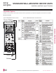
Selecting the Best Location
Do’s
• Place the unit where air circulation will not be blocked.
• Place the unit where drainage can be obtained easily.
• Place the unit where noise prevention is taken into consideration.
• Ensure there is sufficient space from the ceiling and floor.
• Ensure there is sufficient maintenance space.
• Locate the indoor unit where it can be easily connected to the outdoor unit or branch
distribution unit.
Don’ts
• Do not install the unit near a heat or steam source, or where considerable amounts of oil,
iron powder, or flour are used.
•
Do not install the unit where sulfuric acid and flammable or corrosive gases are generated, vented into, or stored.
•
'RQRWLQVWDOOWKHXQLWQHDUKLJKIUHTXHQF\JHQHUDWRUV
• Do not install the unit near a doorway.
The unit will be damaged, will malfunction, and / or will not operate as designed if installed in any of the conditions listed.
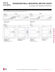
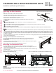
>4 inches
Recommended height
>6-1/2 feet from floor
>4 inches
≥5 inches
)LJXUHMinimum Clearance Requirements.
Installation and Best Layout Practices
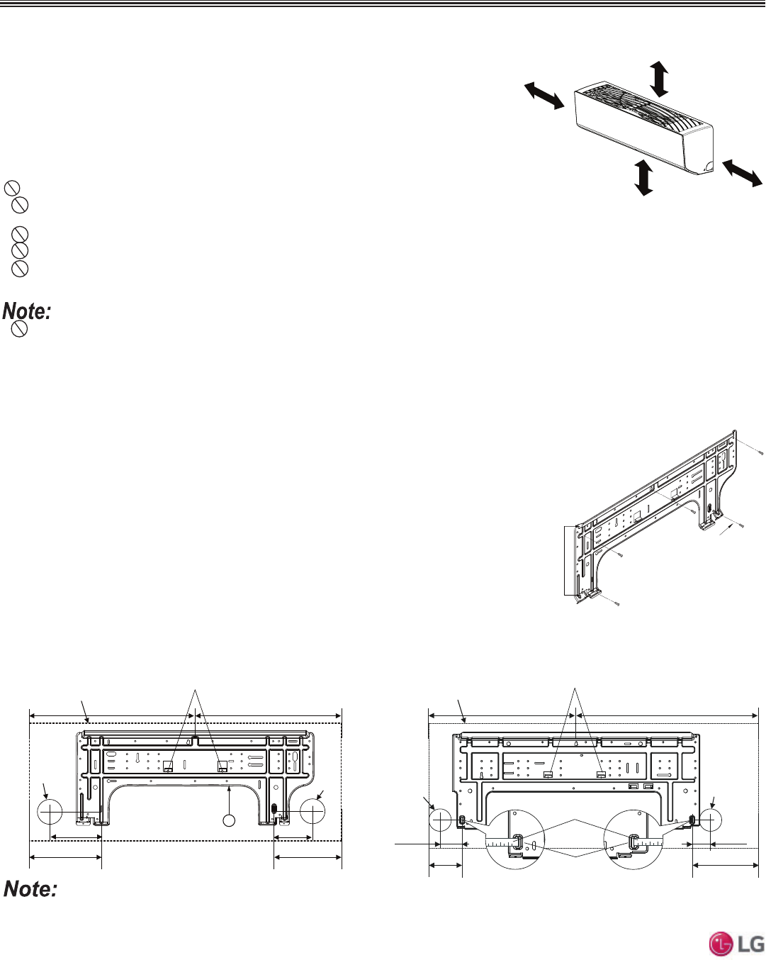
Mounting the Installation Plate
The mounting wall must be strong and solid enough to protect the unit from vibration.
• Mount the installation plate on the wall using the Type “A” screws. If mounting the unit on con-
crete, consider using anchor bolts.
• Always mount the installation plate horizontally. Measure the wall and mark the centerline using
thread and a level.
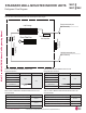
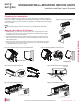
)LJXUHInstallation Plate—
Side View.
Installation Plate
Frame
Hooks
Type "A" Screws
)LJXUHInstallation Plate for LMN079HVT, LSN090HSV5,
LSN120HSV5, and LMN159HVT Units.
)LJXUHInstallation Plate for LSN180HSV5 and LMN249HVT Units.
Ø2-3/4 inches
Ø2-3/4 inches
2-23/32 inches
2-7/32 inches
Right rear
piping
Left rear
piping
Installation Plate
Measuring Tape
Measuring Tape Hanger
Place a level on raised tab
Unit Outline
8-5/32 inches
4-1/8 inches
18-1/8 inches 22-7/16 inches
,IWKHXQLWLVLQVWDOOHGQHDUDERG\RIZDWHUFHUWDLQFRPSRQHQWVDUHDWULVNRIEHLQJFRUURGHG$SSURSULDWHDQWLFRUURVLRQPHWKRGVPXVWEHWDNHQIRUWKH
unit and all components.
STANDARD WALL-MOUNTED INDOOR UNITS
Installing in an Area Exposed to Unconditioned Air
In some installation applications, areas (floors, walls) in some rooms will be exposed to
unconditioned air (room will be above or next to an unheated garage or storeroom). To
FRXQWHUPHDVXUH
• Verify that carpet is or will be installed (carpet will increase the temperature by three degrees).
• Add insulation between the floor joists.
• Install radiant heat or another type of heating system to the floor.
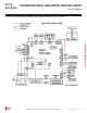
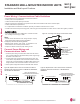
Ø2-9/16
5-3/16 3-11/16
Right rear piping
Left rear piping
Place a level on raised tab
Unit Outline
8-1/2
6-7/8
17-3/8 17-3/8
5
Ø2-9/16
• ,QGRRUXQLWV,'8VPXVWQRWEHSODFHGLQDQHQYLURQPHQWZKHUHWKH,'8VZLOOEHH[SRVHGWRKDUPIXOYRODWLOHRUJDQLFFRPSRXQGV92&V
RULQHQYLURQPHQWVZKHUHWKHUHLVLPSURSHUDLUPDNHXSRUVXSSO\RULQDGHTXDWHYHQWLODWLRQ,IWKHUHDUHFRQFHUQVDERXW92&VLQWKHHQYL
URQPHQWZKHUHWKH,'8VDUHLQVWDOOHGSURSHUDLUPDNHXSRUVXSSO\DQGRUDGHTXDWHYHQWLODWLRQPXVWEHSURYLGHG$GGLWLRQDOO\LQEXLOGLQJV
ZKHUH,'8VZLOOEHH[SRVHGWR92&VFRQVLGHUDWKLUGSDUW\IDFWRU\DSSOLHGHSR[\FRDWLQJWRWKHIDQFRLOVIRUHDFK,'8ZKHUHWKHHQWLUHFRLO
is dipped, not sprayed.
• ,IWKHXQLWLVLQVWDOOHGQHDUDERG\RIZDWHUWKHLQVWDOODWLRQSDUWVDUHDWULVNRIFRUURGLQJ$SSURSULDWHDQWLFRUURVLRQPHWKRGVPXVWEHWDNHQIRU
the unit and all installation parts.