
Multi F Outdoor Condenser Installation Manual

MULTI
F
MAX
MULTI
F
9
Product Data
Due to our policy of continuous product innovation, some specifications may change without notification.
©LG Electronics U.S.A., Inc., Englewood Cliffs, NJ. All rights reserved. “LG” is a registered trademark of LG Corp.
1
Capacity is rated with non-ducted indoor units, 0 ft. above sea level, with a 0 ft. level
difference between outdoor and indoor units, and the following refrigerant pipe lengths:
LMU183HV: 16.4 ft. x 2 = 32.8 ft.
LMU243HV: 16.4 ft. x 3 = 49.2 ft.
LMU303HV: 16.4 ft. x 4 = 65.6 ft.
LMU363HV: 16.4 ft. x 4 = 65.6 ft.
All capacities are net with a combination ratio between 95 – 105%.
Rated cooling capacity obtained with air entering the indoor unit at 80ºF dry bulb (DB) and 67ºF
wet bulb (WB) and outdoor ambient conditions of 95ºF dry bulb (DB) and 75ºF wet bulb (WB).
Rated heating capacity obtained with air entering the indoor unit at 70ºF dry bulb (DB) and
60ºF wet bulb (WB) and outdoor ambient conditions of 47ºF dry bulb (DB) and 43ºF wet bulb (WB).
2
At least two indoor units must be connected. For allocated capacity information, see
the combination tables in the "Multi F / Multi F MAX Combination Data Manual" on www.
lghvac.com. For performance data, see "Multi F / Multi F MAX Performance Data Manual"
on www.lghvac.com.
3
Sound pressure levels are tested in an anechoic chamber under ISO Standard 3745 and
are the same in both cooling and heating mode. These values can increase due to ambient
conditions during operation.
4
3RZHUZLULQJWRWKHRXWGRRUXQLWLV¿HOGVXSSOLHGVROLGRUVWUDQGHGDQGPXVWFRPSO\ZLWK
the applicable local and national codes. For detailed information, please refer to electrical
characteristics on page 10.
5
All power wiring / communication cable to be minimum 14 AWG, 4-conductor from the
outdoor unit to the indoor units, stranded, shielded or unshielded (if shielded, it must be
grounded to the chassis of the outdoor unit only), and must comply with applicable local
and national codes. For detailed electrical information, please refer to electric characteris-
tics on page 10.
6
Piping lengths are equivalent.
7
&RROLQJRSHUDWLRQUDQJHZLWK/RZ$PELHQW:LQG%DIÀH.LWVROGVHSDUDWHO\LV)WR)
8
Operation outside of Continuous Operating Range is subject to safety interruption.
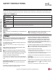
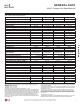
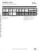
GENERAL DATA
Table 1: 0XOWL)2XWGRRU8QLW6SHFL¿FDWLRQV
0XOWL)2XWGRRU8QLW6SHFL¿FDWLRQV
Model Number LMU183HV LMU243HV LMU303HV LMU363HV
Cooling Capacity (Btu/h)
1
(Min.~Rated~ Max.) 8,400~18,000~21,600 8,400~24,000~25,000 8,400~30,000~36,000 8,400~32,800~38,400
Heating Capacity (Btu/h)
1
(Min.~Rated~ Max.) 10,080~22,000~25,000 10,080~24,600~29,000 10,080~32,000~38,400 10,080~36,000~41,600
Continuous Operating Range
Cooling (°F DB)
7
14 to 118 14 to 118 14 to 118 14 to 118
Heating (°F WB) WR WR WR WR
Operative Operating Range
8
Cooling (°F DB)
7
14 to 122 14 to 122 14 to 122 14 to 122
Heating (°F WB) WR WR WR WR
Compressor
Inverter Quantity Twin Rotary x 1 Twin Rotary x 1 Twin Rotary x 1 Twin Rotary x 1
Oil/Type FVC68D FVC68D FVC68D FVC68D
Fan (Side Discharge)
Type Propeller Propeller Propeller Propeller
Motor Output (W) x Qty. 85.4 x 1 85.4 x 1 124.2 x 1 124.2 x 1
Motor / Drive Brushless Digitally Controlled / Direct
Maximum Air Volume (CFM) 1,766 1,766 2,119 2,119
Unit Data
Refrigerant Type R410A R410A R410A R410A
Refrigerant Control/Location EEV / Outdoor Unit EEV / Outdoor Unit EEV/Outdoor Unit EEV/Outdoor Unit
Min. ~ Max. Number Indoor Units/System
2
2~2 2~3 2~4 2~4
Min. ~ Max. Allowable Total IDU Connected
Capacity (Btu/h)
14,000~24,000 14,000~33,000 14,000~40,000 14,000~48,000
Sound Pressure (Cooling / Heating) dB(A)
3
49 / 54 50 / 54 51 / 54 51 / 54
Dimensions (W x H x D [inch]) 34-1/4 x 25-19/32 x 13 37-13/32 x 32-27/32 x 13
Net / Shipping Unit Weight (lbs.) 101 / 109.8 101.4 / 110.2 138.9 / 154.3 138.9 / 154.3
Power Supply (V, Phase, Hz) 208 / 230V, 1, 60
Power Wiring / Comm. Cable (No. x AWG)
4,5
4C x 14 4C x 14 4C x 14 4C x 14
Heat Exchanger
Material and Fin Coating Copper Tube/Aluminum Fin and GoldFin™/Hydrophilic
Rows / Columns/Fins per inch x Qty. (2 x 28 x 14) x 1 (2 x 28 x 14) x 1 (2 x 38 x 14) x 1 (2 x 38 x 14) x 1
Piping
Liquid Line Connection (in., OD) x Qty. 1/4 x 2 1/4 x 3 1/4 x 4 1/4 x 4
Vapor Line Connection (in., OD) x Qty. 3/8 x 2 3/8 x 3 3/8 x 4 3/8 x 4
Factory Charge lbs. of R410A 3.97 3.97 6.17 6.17
Piping Lengths
Maximum Total Piping (ft.)
6
164.0 230.0 246.1 246.1
Piping Length (No Additional Refrigerant [ft]) 98.4 98.4 98.4 98.4
Min./Max. Outdoor Unit to Indoor Unit Piping (ft) 9.8 / 82.0 9.8 / 82.0 9.8 / 82.0 9.8 / 82.0
Maximum Elevation between ODU and IDU (ft.) 49.2 49.2 49.2 49.2
Maximum Elevation between IDU and IDU (ft.) 24.6 24.6 24.6 24.6