
Engineering Manual

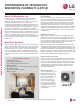

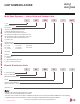


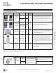
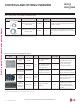
Table Of Contents
- Convergence of Technology, Innovation, Flexibility, & Style
- Unit Nomenclature
- Outdoor Unit Overview
- Indoor Unit Overview
- Controls and Options Overview
- Art Cool Mirror Indoor Units
- General Data / Specifications
- Dimensions
- Cooling Capacity Table
- Heating Capacity Table
- Acoustic Data
- Air Velocity and Temperature Distribution
- Refrigerant Flow Diagram
- Wiring Diagram
- Factory Supplied Parts and Materials
- Installation and Best Layout Practices
- Art Cool Gallery Indoor Units
- General Data / Specifications
- Dimensions
- Cooling Capacity Table
- Heating Capacity Table
- Acoustic Data
- Air Velocity and Temperature Distribution
- Refrigerant Flow Diagram
- Wiring Diagram
- Factory Supplied Parts and Materials
- Installation and Best Layout Practices
- Standard Wall-Mounted Indoor Units
- General Data / Specifications
- Dimensions
- Cooling Capacity Table
- Heating Capacity Table
- Acoustic Data
- Air Velocity and Temperature Distribution
- Refrigerant Flow Diagram
- Wiring Diagram
- Factory Supplied Parts and Materials
- Installation and Best Layout Practices
- Duct (Low Static) Indoor Units
- General Data / Specifications
- Dimensions
- Cooling Capacity Table
- Heating Capacity Table
- External Static Pressure
- Acoustic Data
- Refrigerant Flow Diagrams
- Wiring Diagram
- Factory Supplied Parts and Materials
- Installation and Best Layout Practices
- Duct (High Static) Indoor Units
- General Data / Specifications
- Dimensions
- Cooling Capacity Table
- Heating Capacity Table
- External Static Pressure / Acoustic Data
- Refrigerant Flow Diagrams
- Wiring Diagrams
- Factory Supplied Parts and Materials / Installation
- Installation and Best Layout Practices
- Four-Way Ceiling Cassette Indoor Units
- General Data / Specifications
- Dimensions
- Dimensions
- Cooling Capacity Table
- Heating Capacity Table
- Acoustic Data
- Air Velocity and Temperature Distribution
- Refrigerant Flow Diagram
- Wiring Diagram
- Factory Supplied Parts and Materials
- Installation and Best Layout Practices
- Vertical-Horizontal Indoor Units
- General Data / Specifications
- Dimensions
- Cooling Capacity Table
- Heating Capacity Table
- External Static Pressure
- Acoustic Data
- Refrigerant Flow Diagram
- Wiring Diagram
- Factory Supplied Parts and Materials
- Installation and Best Layout Practices
- Equipment Selection Procedure
- Building Ventilation Design Guide
- Placement Considerations
- Refrigerant Piping Design
- Design Guideline Summary
- Creating a Balanced System / Manual Layout Procedure
- LG Engineered Multi F MAX Y-Branch Kit
- Refrigerant Charge
- Installation & Layout Best Practices
- Refrigerant Piping System Layout
- Piping Insulation
- Condensate Drain Piping
- Y-Branch Kit
- Wiring Connections
- Power Wiring (208-230V) and Communications Cable Details
- Indoor Unit Group Control
- Acronyms

Due to our policy of continuous product innovation, some specications may change without notication.
©LG Electronics U.S.A., Inc., Englewood Cliffs, NJ. All rights reserved. “LG” is a registered trademark of LG Corp.
10 | INTRODUCTION
Multi F and Multi F MAX Indoor Unit Engineering Manual
MULTI
F
MAX
MULTI
F
Before specifying or placing an order, refer to the V-Net Network Solutions Engineering Product Data Book, and review the detailed technical data provided to fully understand the capabilities and limitations of
these devices.
For information on controller capabilities, refer to the Controls and Options Table on page 12.
Specialty Application
Device
Name Model No.
Connects
to
Application
Binary Signals
Input / Output
Description
Dry Contact Unit
24 VAC
PQDSB1
Indoor
Unit
ON / OFF, Run Status,
Error Status
1 / 2
Enables the indoor unit to be
controlled and monitored by
third-party controls using
binary inputs and outputs.
Dry Contact Unit
for Setback
PQDSBC
ON / OFF, Mode, Controller
Lock, Power Save, Run
Status, Error Status
2 / 2
Dry Contact Unit
for Thermostat
PQDSBNGCM1
ON / OFF, Thermo ON /
OFF, Mode, Fan Speed,
Run Status, Error Status
—
Enables the indoor unit to be
controlled and monitored by a
third-party thermostat or controller.
PI-485 V-net
Control
Integration
Board
PMNFP14A1
Outdoor
Unit
— —
Control integration to LG V-net
controls (AC Smart Premium, ACP,
BACnet, LonWorks, etc.)
Power
Distribution
Indicator (PDI)
Premium
PQNUD1S41
Comm.
BUS
Energy Consumption
Monitoring
8 / 0
Monitors total outdoor unit power
consumption for up to eight
systems, and distributes per
indoor unit based on weighted
calculation.
Table 5: Summary Data— Zone Controller Communication Cables.
CONTROLS AND OPTIONS OVERVIEW
Table 6: Summary Data—Specialty Application Devices.
Before specifying or placing an order, refer to the V-Net Network Solutions Engineering Product Data Book, and review the detailed technical data provided to fully understand the capabilities and limitations of
these devices.
For information on controller capabilities, refer to the Controls and Options Table on page 12.
Communication Cable Name Model No.
Max. Wire
Length (ft.)
Description
Wired Remote Group Control
Cable Assembly
PZCWRCG3 32
Required when grouping multiple indoor units with a
single zone controller.
Wired Remote / Group Control
Extension Cable
PZCWRC1 32
Increases the distance between a remote controller
and an indoor unit, or between indoor units in a control
group.