
Multi F Outdoor Unit Engineering Manual


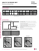


Table Of Contents

MULTI F OUTDOOR UNIT | 119
Multi F Outdoor Unit Data
Due to our policy of continuous product innovation, some specications may change without notication.
©LG Electronics U.S.A., Inc., Englewood Cliffs, NJ. All rights reserved. “LG” is a registered trademark of LG Corp.
MULTI
F
MAX
MULTI
F
Figure 13: LMU369HV Refrigerant Flow Diagram.
Description PCB Connector
Outdoor Air Temperature Thermistor
CN-TH2
Heat Exchanger Temperature Thermistor
Discharge Pipe Temperature Thermistor
CN-TH3
Suction Pipe Temperature Thermistor
Table 114: LMU369HV Thermistor Details.
MULTI F OUTDOOR UNIT
Refrigerant Flow Diagram
Reversing
Valve
Outdoor Unit
Oil Separator
Accumulator
Liquid Piping
Field-installed
Gas Piping
Room D
Room C
Room B
Room A
Compressor
Main Service
Valve (Gas)
Main Service
Valve (Liquid)
Room D
Room C
Room B
Room A
COOLING
HEATING
REFRIGERANT FLOW
S
Heat
Exchanger
Electronic
Expansion Valve-B
Electronic
Expansion Valve-C
Electronic
Expansion Valve-D
Electronic
Expansion Valve-A
Hot
Gas
Bypass
Valve
Field-installed
Discharge Pipe
Temperature
Thermistor
Outdoor Air
Temperature
Thermistor
Heat Exchanger
Temperature
Thermistor
Suction Pipe
Temperature
Thermistor