
Multi F Outdoor Unit Engineering Manual


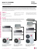


Table Of Contents

MULTI F OUTDOOR UNIT | 17
Multi F Outdoor Unit Data
Due to our policy of continuous product innovation, some specications may change without notication.
©LG Electronics U.S.A., Inc., Englewood Cliffs, NJ. All rights reserved. “LG” is a registered trademark of LG Corp.
MULTI
F
MAX
MULTI
F
Mechanical Specications
MULTI F SYSTEMS
Multi F Heat Pump Condensing Units
General
A Multi F multi-zone system is comprised of one heat pump outdoor
unit connected to two, three, or four indoor units using a shared
refrigerant piping circuit between the outdoor unit and each indoor
unit, and includes integrated controls supplied by LG. The outdoor
unit is internally assembled, wired, and piped from the factory; all LG
components are manufactured in a facility registered to ISO 9001
and ISO 14001, set by the International Organization for Standard-
ization (ISO). The LG Multi F multi zone heat pump system com-
ponents comply with Underwriters Laboratories (UL) 1995 Heating
and Cooling Equipment Standard for Safety, and bear the Electrical
Testing Laboratories (ETL) mark. The units are certified to AHRI 210
/ 240.
Temperature Ranges
The heat pump outdoor units are capable of operating in cooling
mode from 14°F to 118°F ambient dry bulb. The heat pump outdoor
units are capable of operating in heating mode from 0°F to 64°F
ambient wet bulb without additional low ambient controls.
Frame
The Multi F condensing unit case is constructed from pre-coated
metal that has been tested in accordance with ASTM B-117 salt
spray procedure for a minimum of 1,000 hours. Case has a remov-
able front panel to allow access to major components and control
devices, and legs to secure the unit during installation.
Refrigerant System
Multi F systems have a shared refrigerant circuit field piped to
multiple (ducted, non-ducted or mixed) indoor units to effectively and
efficiently control the heating or cooling operation of the multi zone
system. All refrigerant lines from the outdoor unit to the indoor units
are field-installed and must be insulated separately.
All Multi F systems use R410A refrigerant. The outdoor units are
equipped with a refrigerant strainer, check valves, oil separator,
accumulator, four-way reversing valve, electronic expansion valve(s)
(EEV), high side and low side refrigerant charging ports, and a
service port. Each outdoor unit also includes sensors for suction
temperature, discharge temperature, high-pressure, low-pressure,
heat exchanger temperature, and outdoor temperature conditions.
Refrigeration Oil Control
The outdoor units have an oil separator to separate oil mixed with
the refrigerant gas during compression and return oil to the com-
pressor. The outdoor units also have an oil injection mechanism to
ensure a consistent film of oil on all moving compressor parts at low
speed.
Compressor
Multi F condensing units are equipped with one hermetically sealed,
digitally controlled, inverter driven twin-rotary compressor that
includes Teflon™ coated bearings. The inverter motor is capable
of providing a modulation range of 20Hz to 100Hz with control in
1Hz increments. The compressor is protected with phase-reversal
protection, uses a factory-charge of Polyvinyl Ether (PVE) oil, and
is mounted to avoid the transmission of vibration. Compressors in
LMU369HV models are equipped with a hot gas bypass valve.
Fan and Motors
Each 1.5 to 2 ton outdoor unit includes one direct drive variable
speed propeller fan with Brushless Digitally Controlled (BLDC) motor
with a horizontal air discharge. Each 3 ton outdoor unit includes two
direct drive variable speed propeller fans with Brushless Digitally
Controlled (BLDC) motor with a horizontal air discharge.
Fan blades are statically and dynamically balanced propeller fans
made of durable Acrylonitrile Butadiene Styrene (ABS) plastic, and
include a raised fan guard to limit contact with moving parts. The
motors have inherent overload protection, permanently lubricated
bearings, and a maximum speed up to 950 rpm. All Multi F outdoor
units have a horizontal discharge airflow.
Outdoor Unit Coil
The outdoor unit coils are factory-built of aluminum fins mechani-
cally bonded on copper tubing. Coils have a minimum of two rows, a
minimum of 14 fins per inch, and have been factory pressure-tested.
Coil fins also have a factory applied corrosion-resistant GoldFin™
material with hydrophilic coating that has been tested in accordance
with ASTM B-117 salt spray test procedure for a minimum of 1,000
hours.
Electrical
All Multi F outdoor units shall have 208/230V, 1 phase, 60Hz electri-
cal power capable of operating within ±10% of the rated voltage.
Controls
Factory installed microprocessor controls in the outdoor unit and
indoor units shall perform functions to efficiently operate the multi
zone system. System wiring must be installed in a tree configura-
tion from outdoor unit to indoor units through four conductor power/
transmission cable. The system is capable of performing continuous
operation, even when power is turned off to an individual indoor unit.
Figure 4: Multi F LMU187HV and
LMU247HV Outdoor Units.
Figure 5: Multi F LMU369HV
Outdoor Unit.