
Multi F Outdoor Unit Engineering Manual


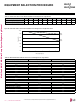


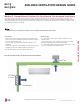


Table Of Contents

EQUIPMENT SELECTION PROCEDURE
Altitude Correction Factor
The impact of air density must be considered on systems installed at a significant altitude above sea level, therefore, locally accepted alti-
tude correction factors must be applied.
Table 161: Outdoor Unit Frost Accumulation Factor (Heating)
1
.
There will be temporary reduction in capacity when frost / ice accumulates on the outside surface of the outdoor unit heat exchanger. The level
of capacity reduction depends on a number of factors, for example, outdoor temperature (°F DB), relative humidity (RH), and the amount of frost
present.
Entering DB (ºF)
19.4 23.0 26.6 32.0 37.4 41.0 44.6
Derate factor
0.98 0.95 0.93 0.86 0.93 0.96 1.0
1
At 85% outdoor air relative humidity.
The frost accumulation factor does not account for effects of snow accumulation restricting airflow
through the outdoor unit coil.
Defrost Correction Factor for Heating Operation
The outdoor unit heating capacity may need to be adjusted for frost accumulation on air-cooled systems. If design day conditions are below
the dewpoint of the surrounding air, frost may not be a problem and no correction factor is needed. In certain weather conditions, however,
frost may form and accumulate on the air-cooled outdoor unit coil and impact the coils ability to transfer heat. If significant frost accumulates
on the outdoor unit coil, a defrost algorithm will start automatically. The timing between defrost periods is determined by the system’s ability
to achieve a target head pressure value.
Capacity and AHRI ratings tables do not factor in capacity reduction when frost has accumulated on the condenser coil, nor during defrost
operation.
Integrated heating capacity values can be obtained using the formula:
A = B x C
Where:
A = Integrated Heating Capacity.
B = Value found in the Capacity Table.
C = Correction Factor for Frost Accumulation Factor (from Table 161).
Check the Indoor and Outdoor Unit Selection(s)
Compare the corrected cooling and heating capacities to the load calculations. Is each capacity sufficient for the zone it serves?
For each indoor unit, the corrected capacity must be at least equal to the total of the cooling design load (plus ventilation load, if applicable)
for the space(s) served by the indoor unit. For each indoor unit, the corrected capacity also must be at least equal to the total of the heating
design load (plus ventilation load, if applicable) for the space(s) and / or thermal zones served by the indoor unit.
The outdoor unit selected should be large enough to offset the total cooling load for all spaces it serves (account for ventilation air cooling
load if the ventilation air has not been pretreated to room neutral conditions). The outdoor unit should also be large enough to offset the total
heating load for all spaces it serves.
If the corrected heating capacity ratio exceeds 100%, reselect the equipment, or change the system design by moving some of the load to
another system.
•Understand the design safety factors.
•Reference load calculations for actual cooling and heating capaci-
ties (applies in 99% of applications – consider total load when
latent load is greater than 30%).
•Verify that the sensible load of the zone is satisfied.
•Use caution when sizing to meet listed capacity specifications for
the scheduled manufacturer’s equipment.
If further system design assistance is needed, or you have a unique
application you would like to discuss, contact your LG sales rep.
1. Outdoor Unit Rated Capacity.
Q
odu(rated)
(From capacity tables).
2. Outdoor Unit Capacity at Ti, To Temperature.
Q
odu(Ti, To)
(From capacity tables).
3 Outdoor Unit Capacity Coefficient Factor.
F
(Ti, To)
= Q
odu(Ti, To)
/ Q
odu(rated)
4. Piping Correction Factor (From Capacity Coefficient
Factor Tables).
F
(length)
for each piping length
5. Individual Indoor Unit Combination Capacity.
Q
idu (combi)
= Q
odu(rated)
x Q
idu(rated)
/ Q
idu(rated-total)
6. Individual Indoor Unit Actual Capacity.
Q
idu (actual)
= Q
odu(combi)
x F
(Ti, To)
x F
(length, altitude)
System Sizing Check Formulas
Conclusions and Recommendations
Due to our policy of continuous product innovation, some specications may change without notication.
©LG Electronics U.S.A., Inc., Englewood Cliffs, NJ. All rights reserved. “LG” is a registered trademark of LG Corp.
ApplicAtion Guidelines | 185
Application Guidelines
MULTI
F
MAX
MULTI
F