
Multi F Outdoor Unit Engineering Manual


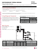


Table Of Contents

Tie-Downs and Lightening Protection
Tie-Downs
•The strength of the roof must be checked before installing the
outdoor units.
•If the installation site is prone to high winds or earthquakes, when
installing on the wall or roof, securely anchor the mounting base
using a field-provided tie-down configuration approved by a local
professional engineer.
•The overall tie-down configuration must be approved by a local
professional engineer. Always refer to local code when using a
wind restraint system.
Lightening Protection
•To protect the outdoor unit from lightning, it should be placed within
the specified lightning safety zone.
•Power cable and communication cable should be installed five (5)
feet away from lightning rod.
•A high-resistance ground system should be included to protect
against induced lightning or indirect strike.
Ground
Safe zone
Lightning rod
Protection Angle (25˚~55˚)
1.5m
5 feet
Lightning rod
Figure 47: Lightening Protection Diagram.
Table 163:SafetyZoneSpecications.
Building Height (feet)
66 98 148 197
ProtectionAngle(˚)
55 45 35 25
If the building does not include lightning protection, the outdoor unit
may be damaged from a lightening strike. Inform the customer of
this possibility in advance.
Minimum 11-13/16
Air inlet grille
Blown
air
Strong
wind
Strong
wind
Minimum 11-13/16
23-5/8
Sunroof
Fence or
obstacles
Minimum 11-13/16
Air inlet grille
Blown
air
Strong
wind
Strong
wind
Minimum 19-1/16
Fence or
obstacles
Unit: Inch
Minimum 11-13/16
Ensure that the space at the back of the outdoor unit is a minimum of 11-13/16 inches, and
include a minimum of 23-5/8 inches at the right side of the unit for service.
If the outdoor unit discharge side faces a wall, include a minimum of 19-11/16 inches
between the outdoor unit and the wall. Install the outdoor unit so that the discharge port is
set at a right angle to the wind direction.
Outdoor Unit Service Access and Allowable Clearances
Appropriate airflow through the outdoor unit coil is critical for proper unit operation.
•Include enough space for airflow and for service access. If installing multiple outdoor units, avoid placing the units where the discharge of
one unit will blow into the inlet side of an adjacent unit.
•No obstacles to air circulation around the unit; keep proper distances from ceilings, fences, floor, walls, etc. (Install a fence to prevent pests
from damaging the unit or unauthorized individuals from accessing it.)
•If an awning is built over the unit to prevent direct sunlight or rain exposure, make sure that the discharge air of the outdoor unit isn’t restricted.
When installing the outdoor unit, consider service, inlet, and outlet, and minimum allowable space requirements as illustrated in the following
diagrams.
PLACEMENT CONSIDERATIONS
Due to our policy of continuous product innovation, some specications may change without notication.
©LG Electronics U.S.A., Inc., Englewood Cliffs, NJ. All rights reserved. “LG” is a registered trademark of LG Corp.
194 | ApplicAtion Guidelines
Multi F and Multi F MAX Heat Pump System Engineering Manual
MULTI
F
MAX
MULTI
F