
Multi F Outdoor Unit Engineering Manual


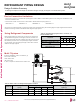


Table Of Contents

Creating a Balanced / Quality Piping System
Unlike designing duct-work or chilled and hot water pipe systems where balancing dampers, ball valves, orifices, circuit setters, or other
flow control devices can be installed to modify or balance the flow of cooling medium, these cannot be used in a Multi F system. Therefore,
variable refrigerant flow systems have to be designed to be “self balanced.” Balanced liquid refrigerant distribution is solely dependent on
the designer using the correct pipe size for each segment. Pipe sizing considerations include pipe length, pipe segment pressure drop
relative to other pipe segments in the system, type and quantity of elbows, bends present, fitting installation orientation, and end use device
elevation differences.
Any eld changes, such as re-routing, shortening or lengthening a pipe segment, adding or eliminating elbows and/or ttings, re-sizing, adding,
or eliminating indoor units, changing the mounting height or moving the location of a device or tting during installation should be done with cau-
tion and ALWAYS VERIFIED in LATS MULTI SOFTWARE before supplies are purchased or installed. Doing so ensures protable installation,
eliminates rework, and ensures easier system commissioning.
The designer should avoid creating excessive pressure drop. When liquid refrigerant is subjected to excessive pressure drop, liquid refrig-
erant will change state and “ash” to vapor. Vapor present in a stream of liquid refrigerant before reaching the indoor unit coil (or branch
distribution unit for Multi F MAX systems) results in a loss of system control and causes damage to the components. The pipe system must
be designed in a manner that avoids the creation of unwanted vapor.
Refrigerant Piping System Verification
To ensure that the refrigerant piping design is suitable for the system, a LATS refrigerant piping design software report must be provided with
every Multi F order. Following the installation, if any changes or variations to the design were necessary, an “as-built” LATS piping design
software report must be provided to LG prior to system commissioning. User should always check the LATS report actual pipe layout versus
pipe limits.
REFRIGERANT PIPING DESIGN
Manual Layout Procedure
1. Choose the location of the indoor units on the building drawing.
2. Choose the location of all Y-branch and branch distribution units (if a Multi F MAX system) and note them on the building drawing. Verify
that all fittings are positioned per the guideline limitations set forth in “Y-branch Kits” on page 201.
3. Plan the route for interconnecting piping. Draw a one-line depiction of the pipe route chosen on the building drawing.
4. Calculate the actual length of each pipe segment and note it on the building drawing.
5. Using the data obtained while selecting the system components on page 180 to 185, list the corrected cooling capacity next to each
indoor unit on the drawing.
6. Starting at the indoor unit located farthest from the outdoor unit, sum the corrected cooling capacity of all indoor units served by the pipe
segmentforeachbranchandrunoutpipe(indoorunitsandbranchdistributionunits[MultiFMAXsystemsonly]).Recordthesevalues
next to each segment.
7. Verify the size of the liquid and vapor lines.
8. If a Multi F MAX system, refer to Cut-Sheets “Y-branch Kits” on page 217 and branch distribution units on page 172 to verify the part
number of each Y-branch and branch distribution unit based on the connected downstream nominal capacity served.
9. Calculate the equivalent pipe length in feet of each pipe segment. If a Multi F MAX system, Y-branch equivalent lengths should be totaled
with the upstream segment only. Use equivalent pipe length data when it is provided with field-purchased fittings. If not available, use
the data provided on page 165 to estimate the equivalent length of field-provided pipe and fittings for each segment. Equivalent lengths
should be totaled with the upstream segment only.
10. Verify if the equivalent pipe length complies with the limitations in the “Multi F and Multi F MAX Refrigerant Piping System Limitations”
tables on pages 166 and 167. If the limitations are exceeded, either reroute the pipe or change the location of the indoor unit, Y-branch
fittings and branch distribution units (if Multi F MAX systems), so the design conforms with all limitations.
11. If adjusted as per Step 10 above, verify again if the length of the design complies with the limitations set in “Multi F and Multi F MAX
Refrigerant Piping System Limitations” tables on pages 166 and 167.
12. Verify that the manually sized pipe design is acceptable using LATS Multi. When entering the length of pipe segments in LATS Multi
software, enter the equivalent pipe length. Account for the additional pressure drop created by elbows, valves, and other fittings present in
each segment by adding their respective equivalent pipe length to the actual pipe length.
Creating a Balanced System / Manual Layout Procedure
Due to our policy of continuous product innovation, some specications may change without notication.
©LG Electronics U.S.A., Inc., Englewood Cliffs, NJ. All rights reserved. “LG” is a registered trademark of LG Corp.
200 | DESIGN & PRACTICES
Multi F and Multi F MAX Heat Pump System Engineering Manual
MULTI
F
MAX
MULTI
F