
Multi F Outdoor Unit Engineering Manual


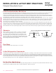


Table Of Contents

Pipe
Length
1
Fluid Temperature °F
35° 40° 45° 50° 55° 60° 65° 70° 75° 80° 85° 90° 95° 100° 105° 110° 115° 120° 125° 130°
10
0.04 0.04 0.05 0.06 0.06 0.07 0.08 0.08 0.09 0.09 0.10 0.10 0.11 0.11 0.11 0.12 0.13 0.14 0.15 0.15
20
0.08 0.08 0.10 0.12 0.13 0.14 0.15 0.16 0.17 0.18 0.19 0.20 0.21 0.22 0.22 0.23 0.26 0.28 0.29 0.30
30
0.12 0.12 0.15 0.18 0.20 0.21 0.23 0.24 0.26 0.27 0.29 0.30 0.32 0.33 0.32 0.35 0.39 0.42 0.44 0.45
40
0.16 0.16 0.20 0.24 0.26 0.28 0.30 0.32 0.34 0.36 0.38 0.40 0.42 0.44 0.43 0.46 0.52 0.56 0.58 0.60
50
0.20 0.20 0.25 0.30 0.33 0.35 0.38 0.40 0.43 0.45 0.48 0.50 0.53 0.55 0.54 0.58 0.65 0.70 0.73 0.75
60
0.24 0.24 0.30 0.36 0.39 0.42 0.45 0.48 0.51 0.54 0.57 0.60 0.63 0.66 0.65 0.69 0.78 0.84 0.87 0.90
70
0.28 0.28 0.35 0.42 0.46 0.49 0.53 0.56 0.60 0.63 0.67 0.70 0.74 0.77 0.76 0.81 0.91 0.98 1.02 1.05
80
0.32 0.32 0.40 0.48 0.52 0.56 0.60 0.64 0.68 0.72 0.76 0.80 0.84 0.88 0.86 0.92 1.04 1.12 1.16 1.20
90
0.36 0.36 0.45 0.54 0.59 0.63 0.68 0.72 0.77 0.81 0.86 0.90 0.95 0.99 0.97 1.04 1.17 1.26 1.31 1.35
100
0.40 0.40 0.50 0.60 0.65 0.70 0.75 0.80 0.85 0.90 0.95 1.00 1.05 1.10 1.08 1.15 1.30 1.40 1.45 1.50
120
0.48 0.48 0.60 0.72 0.78 0.84 0.90 0.96 1.02 1.08 1.14 1.20 1.26 1.32 1.30 1.38 1.56 1.68 1.74 1.80
140
0.56 0.56 0.70 0.84 0.91 0.98 1.05 1.12 1.19 1.26 1.33 1.40 1.47 1.54 1.51 1.61 1.82 1.96 2.03 2.10
160
0.64 0.64 0.80 0.96 1.04 1.12 1.20 1.28 1.36 1.44 1.52 1.60 1.68 1.76 1.73 1.84 2.08 2.24 2.32 2.40
180
0.72 0.72 0.90 1.08 1.17 1.26 1.35 1.44 1.53 1.62 1.71 1.80 1.89 1.98 1.94 2.07 2.34 2.52 2.61 2.70
1
Pipe length baseline temperature = 0°F. "Expansion of Carbon, Copper and Stainless Steel Pipe," The Engineers' Toolbox, www.engineeringtoolbox.com.
Table 175: Linear Thermal Expansion of Copper Tubing in Inches.
Selecting Field-Supplied Copper Tubing
INSTALLATION & LAYOUT BEST PRACTICES
Large Tubing U-bend (>3/4 in.) Loop
Small Tubing U-bend (<3/4 in.)
Figure 55: Coiled Expansion Loops and Offsets.
R
L
L
R
L
Table 176: Radii of Coiled Expansion Loops and Developed Lengths of Expansion Offsets.
R
L
L
R
L
R
L
L
R
L
Anticipated Linear Expansion (LE) (inches)
Nominal Tube Size (OD) inches
1/4 3/8 1/2 3/4
1/2
R
1
6 7 8 9
L
2
38 44 50 59
1
R
1
9 10 11 13
L
2
54 63 70 83
1-1/2
R
1
11 12 14 16
L
2
66 77 86 101
2
R
1
12 14 16 19
L
2
77 89 99 117
2-1/2
R
1
14 16 18 21
L
2
86 99 111 131
3
R
1
15 17 19 23
L
2
94 109 122 143
3-1/2
R
1
16 19 21 25
L
2
102 117 131 155
4
R
1
17 20 22 26
L
2
109 126 140 166
1
R = Centerline Length of Pipe.
2
L = Centerline Minimum Radius (inches).
Due to our policy of continuous product innovation, some specications may change without notication.
©LG Electronics U.S.A., Inc., Englewood Cliffs, NJ. All rights reserved. “LG” is a registered trademark of LG Corp.
DESIGN & PRACTICES | 205
Refrigerant Piping Design and Best Practices
MULTI
F
MAX
MULTI
F