
Multi F Outdoor Unit Engineering Manual


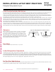


Table Of Contents

Field-Provided Isolation Ball Valves
LG recommends installing field-supplied ball valves with Schrader ports at each indoor unit. Full-port isolation ball valves with Schrader ports
(positioned between valve and indoor unit) rated for use with R410A refrigerant should be used on both the liquid and vapor lines.
If valves are not installed and a single indoor unit needs to be removed or repaired, the entire system must be shut down and evacuated. If
isolation ball valves are installed, and an indoor unit needs to be repaired, the unaffected indoor units can remain operational with readdress-
ing and the proper combination ratio. Reclamation of refrigerant, then, can be restricted to a single indoor unit.
For Multi F MAX systems, position valves with a minimum distance of three (3) to six (6) inches of pipe on either side of the valve, and placed
between six (6) and twelve (12) inches from the first upstream Y-branch or branch distribution unit. If ball valves are installed away from the
first Y-branch and / or branch distribution unit and closer to the indoor unit, oil may accumulate where it cannot be returned to the outdoor
unit and may cause a shortage of oil in the compressor.
Valves shall be easily accessible for service. If necessary, install drywall access doors or removable ceiling panels, and position the valves
to face the access door or ceiling panel opening. Mount valves with adequate space between them to allow for placement of adequate pipe
insulation around the valves. Recommended best practice is to clearly label and document locations of all service valves, Y-branches, and
branch distribution units. The equivalent pipe length of each ball valve must be added to each pipe segment entered into the LATS program.
Figure 56: Installing Piping Above and Below an Obstacle.
Above an obstacle.
3X
Minimum
Below an obstacle.
Obstacles
When an obstacle, such as an I-beam or concrete T, is in the path
of the planned refrigerant pipe run, it is best practice to route the
pipe over the obstacle. If adequate space is not available to route
the insulated pipe over the obstacle, then route the pipe under the
obstacle. In either case, it is imperative the horizontal section of pipe
above or below the obstacle be a minimum of three (3) times greater
than the longest vertical rise (or fall) distance.
Refrigerant Piping System Layout
INSTALLATION & LAYOUT BEST PRACTICES
Pipe Slope
The horizontal pipe slope cannot exceed 10° up or down.
In-line Refrigeration Components
Components such as oil traps, solenoid valves, filter-dryers, sight glasses, tee fittings, and other after-market accessories are not permitted
on the refrigerant piping system between the outdoor units and the indoor / branch distribution units. Multi F and Multi F MAX systems are
provided with redundant systems that assure oil is properly returned to the compressor. Sight-glasses and solenoid valves may cause vapor
to form in the liquid stream. Over time, dryers may deteriorate and introduce debris into the system. The designer and installer should verify
the refrigerant piping system is free of traps, sagging pipes, sight glasses, filter dryers, etc.
No Pipe Size Substitutions
Use only the pipe size selected by the LATS Multi pipe system design software or as conveyed in the product installation instructions. Using
a different size is prohibited and may result in a system malfunction or failure to work at all.
Due to our policy of continuous product innovation, some specications may change without notication.
©LG Electronics U.S.A., Inc., Englewood Cliffs, NJ. All rights reserved. “LG” is a registered trademark of LG Corp.
206 | DESIGN & PRACTICES
Multi F and Multi F MAX Heat Pump System Engineering Manual
MULTI
F
MAX
MULTI
F