
Multi F Outdoor Unit Engineering Manual


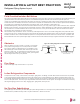


Table Of Contents

INSTALLATION & LAYOUT BEST PRACTICES
Refrigerant Piping System Layout
Examples of Supports
Bolt
1.5t
Plate
Insulation
Bolt
PVC
PVC
Figure 62: U-Bolt Support with Insulation. Figure 63: O-Ring Support with Insulation.
To prevent
insulation from
pressing and
lagging, use a cover.
Sheathing
Sheathing
O-Ring
Band
Lags
Do not compress the insulation with the saddle-type support. If the insulation is compressed, it may tear open and allow condensation to
generate during product operation.
Welding
Refrigerant Pipe
Insulated
Support Band
Insulated
Support Band
Down
Stop
Welding
Plate Nut
Hexagonal Nut
O-ring Band
Support at Intervals Between 5 and 6-3/4 Feet
Figure 64: Saddle-Type Support.
Figure 65: U-Bolt Support with an Insulated Pipe. Figure 66: O-Ring Band Support with an Insulated Pipe.
Figure 67: One-Point Down-Stop Support (>441 lbs.).
Figure 68: Two-Point Down-Stop Support.
Due to our policy of continuous product innovation, some specications may change without notication.
©LG Electronics U.S.A., Inc., Englewood Cliffs, NJ. All rights reserved. “LG” is a registered trademark of LG Corp.
208 | DESIGN & PRACTICES
Multi F and Multi F MAX Heat Pump System Engineering Manual
MULTI
F
MAX
MULTI
F