
Engineering Manual


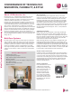

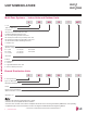
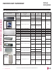
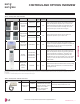
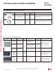
Table Of Contents
- Convergence of Technology, Innovation, Flexibility, & Style
- Unit Nomenclature
- Outdoor Unit Overview
- Indoor Unit Overview
- Controls and Options Overview
- Art Cool Mirror Indoor Units
- General Data / Specifications
- Dimensions
- Cooling Capacity Table
- Heating Capacity Table
- Acoustic Data
- Air Velocity and Temperature Distribution
- Refrigerant Flow Diagram
- Wiring Diagram
- Factory Supplied Parts and Materials
- Installation and Best Layout Practices
- Art Cool Gallery Indoor Units
- General Data / Specifications
- Dimensions
- Cooling Capacity Table
- Heating Capacity Table
- Acoustic Data
- Air Velocity and Temperature Distribution
- Refrigerant Flow Diagram
- Wiring Diagram
- Factory Supplied Parts and Materials
- Installation and Best Layout Practices
- Standard Wall-Mounted Indoor Units
- General Data / Specifications
- Dimensions
- Cooling Capacity Table
- Heating Capacity Table
- Acoustic Data
- Air Velocity and Temperature Distribution
- Refrigerant Flow Diagram
- Wiring Diagram
- Factory Supplied Parts and Materials
- Installation and Best Layout Practices
- Duct (Low Static) Indoor Units
- General Data / Specifications
- Dimensions
- Cooling Capacity Table
- Heating Capacity Table
- External Static Pressure
- Acoustic Data
- Refrigerant Flow Diagrams
- Wiring Diagram
- Factory Supplied Parts and Materials
- Installation and Best Layout Practices
- Duct (High Static) Indoor Units
- General Data / Specifications
- Dimensions
- Cooling Capacity Table
- Heating Capacity Table
- External Static Pressure / Acoustic Data
- Refrigerant Flow Diagrams
- Wiring Diagrams
- Factory Supplied Parts and Materials / Installation
- Installation and Best Layout Practices
- Four-Way Ceiling Cassette Indoor Units
- General Data / Specifications
- Dimensions
- Dimensions
- Cooling Capacity Table
- Heating Capacity Table
- Acoustic Data
- Air Velocity and Temperature Distribution
- Refrigerant Flow Diagram
- Wiring Diagram
- Factory Supplied Parts and Materials
- Installation and Best Layout Practices
- Vertical-Horizontal Indoor Units
- General Data / Specifications
- Dimensions
- Cooling Capacity Table
- Heating Capacity Table
- External Static Pressure
- Acoustic Data
- Refrigerant Flow Diagram
- Wiring Diagram
- Factory Supplied Parts and Materials
- Installation and Best Layout Practices
- Equipment Selection Procedure
- Building Ventilation Design Guide
- Placement Considerations
- Refrigerant Piping Design
- Design Guideline Summary
- Creating a Balanced System / Manual Layout Procedure
- LG Engineered Multi F MAX Y-Branch Kit
- Refrigerant Charge
- Installation & Layout Best Practices
- Refrigerant Piping System Layout
- Piping Insulation
- Condensate Drain Piping
- Y-Branch Kit
- Wiring Connections
- Power Wiring (208-230V) and Communications Cable Details
- Indoor Unit Group Control
- Acronyms

Due to our policy of continuous product innovation, some specications may change without notication.
©LG Electronics U.S.A., Inc., Englewood Cliffs, NJ. All rights reserved. “LG” is a registered trademark of LG Corp.
6 | INTRODUCTION
Multi F and Multi F MAX Indoor Unit Engineering Manual
MULTI
F
MAX
MULTI
F
UNIT NOMENCLATURE
Multi-Zone Systems — Indoor Units and Outdoor Units
M
AN 12 7 HVT
Generation
Features:
H = Heat Pump
V = Inverter
T = High Wall-Mounted Indoor Unit
P = Art Cool Gallery Indoor Unit
Nominal Capacity
(Nominal cooling capacity in Btu/h):
Component:
AN: Art Cool™ Wall-Mounted Indoor Unit
N: Standard Wall-Mounted Indoor Unit
CN: Four-Way Ceiling-Cassette Indoor Unit
DN: Ceiling-Concealed Duct (Low Static) Indoor Unit
HN: Ceiling-Concealed Duct (High Static) Indoor Unit
VN: Vertical-Horizontal Air Handling Indoor Unit
U: Outdoor Unit
L = LG
07 = 7,000
09 = 9,000
12 = 12,000
15 = 15,000
18 = 18,000
24 = 24,000
36 = 36,000
54 = 54,000
L
Type: M = Multi-Zone
Branch Distribution Units
M
BD 36
BD: Branch Distribution Unit
P = Part (Accessory)
P
Type: M = Multi-Zone
Family
Number of Port Connections
(Maximum Number of Connectable Indoor Units): 2, 3, 4
Generation: 0, 1
02
• Voltage for all equipment is 208-230V, 60 Hz, 1-phase.
• All indoor units are compatible with wired controllers
• All outdoor units are LGAP control network compatible with PI-485 V-net Control Integration Board (PMNFP14A1, sold separately).
• Compatible single zone IDU nomenclature is listed in the Single Zone Wall-Mounted IDU Engineering Manual.