
Engineering Manual


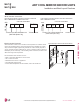


Table Of Contents
- Convergence of Technology, Innovation, Flexibility, & Style
- Unit Nomenclature
- Outdoor Unit Overview
- Indoor Unit Overview
- Controls and Options Overview
- Art Cool Mirror Indoor Units
- General Data / Specifications
- Dimensions
- Cooling Capacity Table
- Heating Capacity Table
- Acoustic Data
- Air Velocity and Temperature Distribution
- Refrigerant Flow Diagram
- Wiring Diagram
- Factory Supplied Parts and Materials
- Installation and Best Layout Practices
- Art Cool Gallery Indoor Units
- General Data / Specifications
- Dimensions
- Cooling Capacity Table
- Heating Capacity Table
- Acoustic Data
- Air Velocity and Temperature Distribution
- Refrigerant Flow Diagram
- Wiring Diagram
- Factory Supplied Parts and Materials
- Installation and Best Layout Practices
- Standard Wall-Mounted Indoor Units
- General Data / Specifications
- Dimensions
- Cooling Capacity Table
- Heating Capacity Table
- Acoustic Data
- Air Velocity and Temperature Distribution
- Refrigerant Flow Diagram
- Wiring Diagram
- Factory Supplied Parts and Materials
- Installation and Best Layout Practices
- Duct (Low Static) Indoor Units
- General Data / Specifications
- Dimensions
- Cooling Capacity Table
- Heating Capacity Table
- External Static Pressure
- Acoustic Data
- Refrigerant Flow Diagrams
- Wiring Diagram
- Factory Supplied Parts and Materials
- Installation and Best Layout Practices
- Duct (High Static) Indoor Units
- General Data / Specifications
- Dimensions
- Cooling Capacity Table
- Heating Capacity Table
- External Static Pressure / Acoustic Data
- Refrigerant Flow Diagrams
- Wiring Diagrams
- Factory Supplied Parts and Materials / Installation
- Installation and Best Layout Practices
- Four-Way Ceiling Cassette Indoor Units
- General Data / Specifications
- Dimensions
- Dimensions
- Cooling Capacity Table
- Heating Capacity Table
- Acoustic Data
- Air Velocity and Temperature Distribution
- Refrigerant Flow Diagram
- Wiring Diagram
- Factory Supplied Parts and Materials
- Installation and Best Layout Practices
- Vertical-Horizontal Indoor Units
- General Data / Specifications
- Dimensions
- Cooling Capacity Table
- Heating Capacity Table
- External Static Pressure
- Acoustic Data
- Refrigerant Flow Diagram
- Wiring Diagram
- Factory Supplied Parts and Materials
- Installation and Best Layout Practices
- Equipment Selection Procedure
- Building Ventilation Design Guide
- Placement Considerations
- Refrigerant Piping Design
- Design Guideline Summary
- Creating a Balanced System / Manual Layout Procedure
- LG Engineered Multi F MAX Y-Branch Kit
- Refrigerant Charge
- Installation & Layout Best Practices
- Refrigerant Piping System Layout
- Piping Insulation
- Condensate Drain Piping
- Y-Branch Kit
- Wiring Connections
- Power Wiring (208-230V) and Communications Cable Details
- Indoor Unit Group Control
- Acronyms

Finalizing Indoor Unit Installation
1. Move the tubing clamp to its original position.
2. Ensure the three (3) hooks are properly attached to the installa-
tion plate by gently shaking the indoor unit from side to side.
3. Press the bottom left and right sides of the indoor unit against the
installation plate until the hooks click firmly into their slots.
4. Using two (2) Type “C” screws, secure the bottom of the indoor
unit to the installation plate.
5. Remove the two (2) tabs from the filter.
6. Replace the frame cover.
Type 'C' screws
Figure 35:Removing the Cable Guide Grooves.
ART COOL MIRROR INDOOR UNITS
Installation and Best Layout Practices
Assigning the Thermistor for Temperature Detection
Each indoor unit includes a return air thermistor assigned to sense the temperature. If a wired controller is installed, there is a choice of
sensing temperature with either the indoor unit return air thermistor or the thermistor in the wired controller. It is also an option to set both
thermistors to sense temperature so that indoor unit bases its operation on the first thermistor to reach the designated temperature differen-
tial. For applicable indoor units, an optional Remote Temperature Sensor can be used in lieu of the return air thermistor—either alone or in
conjunction with a wired controller thermistor as previously described.
Hanging the Wired Controller
1. The controller wiring / cable can be installed in one of three direc-
tions: top, back, or on the right side. If top or right side installation
is desired, remove cable guide grooves on the controller, and
then position wiring / cable on applicable side.
2. Choose and mark the area of installation, and then screw the wall
plate into place (using the provided parts). Install the controller
wall plate to fit the electrical box if one is present. Ensure that no
gaps exist between the wall plate and the wall itself.
3. Arrange wiring / cables so as not to interfere with the controller
circuitry. Position the wired controller on the wall plate. Snap into
place by pressing the bottom part of the wired controller onto
the wall plate. Make sure that no gaps exist between the wired
controller and the wall plate on all sides.
4. To remove wired controller from the wall plate, insert a screw-
driver into the two holes at the bottom. Twist screwdriver to
release controller. Do not damage the controller components
when removing.
Back
Top
Top
Right
Side
Right
Side
Wall Wall
Wall Wall
Installing the Controller
Removing the Controller
Figure 36:Attaching the Wall Plate. Figure 37:Installing / Removing
the Controller.
Figure 38:Attach the bottom of the indoor unit to the installation plate.
Figure 39:Removing the Filter Tabs.
Filter
Due to our policy of continuous product innovation, some specications may change without notication.
©LG Electronics U.S.A., Inc., Englewood Cliffs, NJ. All rights reserved. “LG” is a registered trademark of LG Corp.
36 | ART COOL MIRROR
Multi F and Multi F MAX Indoor Unit Engineering Manual
MULTI
F
MAX
MULTI
F