
Multi F Outdoor Condenser Installation Manual


85
Final Installation Procedures
Due to our policy of continuous product innovation, some specifications may change without notification.
©LG Electronics U.S.A., Inc., Englewood Cliffs, NJ. All rights reserved. “LG” is a registered trademark of LG Corp.
MULTI
F
MAX
MULTI
F
Test Run
After the triple leak / pressure and evacuation procedures are com-
plete, perform a test run.
Before the Test Run
1. Check that all condensate tubing, refrigerant piping and power
wiring, and communication / connection (power) cables are prop-
erly connected.
2. Make sure that the gas and liquid service valves are fully open.
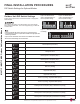
Refrigerant
Type
Outside Ambient
Temperature
Gas Side Service
Valve Pressure
R410A ) 113~142 psig
If the pressure is >142 psig, the system is most likely overcharged, and refrigerant must be removed. If the pressure is <113 psig, the system is most
likely undercharged and refrigerant must be added.
Outlet
Temperature
Discharge Air
Inlet Temperature
Outlet
Temperature
Discharge Air
Inlet Temperature
Outlet
Temperature
Discharge Air
Inlet Temperature
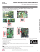
Figure 106: Piping Connection on the Outdoor Unit (Will Differ Depend-
ing on Outdoor Unit Model).
Figure 107: Inlet and Outlet Temperature Locations on Various Indoor Units.
Installing the Remote Controller Batteries
As part of the test run, the batteries need to be inserted into the remote
controller, and the remote controller will need to be powered on to
operate the indoor units (depending on the indoor units included in the
system). To insert the batteries, follow the steps below. For information
on using the remote controller, refer to its owner’s manual.
1. The remote controller needs two (2) AAA (1.5V) batteries for oper-
ation.
Do not use rechargeable batteries. Remove the battery
cover from the back of the remote controller by pushing downward
on the tab at the top of the battery cover and then lift up to remove.
2. Insert the two new batteries. Align batteries by the (+) and (-) sides (the interior battery compartment of the remote controller will have
clear markings for the (+) and (-) placement).
3. Verify that the batteries have “clicked” into the compartment and are firmly engaged with the contacts on either side.
4. Reattach the back cover of the remote controller.
5. Proceed with powering on the remote controller and usage as needed.
Test Run Procedure
1. Operate the system in cooling mode for 15 to 20 minutes.
2. Evaluate performance as the system runs, verifying the outdoor unit, and all indoor units and branch distribution units (Multi F MAX sys-
tems only) are working properly. Make notes as needed to address any issues that might be found.
• Check the system refrigerant charge:
• Measure the pressure from the gas side service valve.
• Measure the indoor unit inlet and outlet air temperatures. Verify the difference between the intake temperature and the discharge is
PRUHWKDQ)
• See table below for the optimum condition of the gas side pressure (again, system is in cooling mode).
Figure 108: Installing the Remote Controller Batteries.
Table 37: Optimum Conditions of the Gas Side Pressure.
7HVW5XQ
FINAL INSTALLATION PROCEDURES
Bolt
Refrigerant Pipe
Connection Location
Top of Outdoor Unit
(Looking Down)
Bolt
Bolt
Bolt