
Wall Mounted Installation Manual


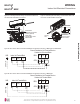

Table Of Contents

46
Multi F Standard Wall-Mounted Indoor Unit
Due to our policy of continuous product innovation, some specifications may change without notification.
©LG Electronics U.S.A., Inc., Englewood Cliffs, NJ. All rights reserved. “LG” is a registered trademark of LG Corp.
MAX
MULTI
F
MULTI
F
HVT Indoor Unit Wiring Installation Procedure
1. The front panel must already be opened, and the bottom panel must al-
ready be removed. If not, fully open the front panel. The control cover can
be accessed on the bottom right side of the front of the indoor unit.
2. At the bottom panel of the indoor unit, unsnap the latches that cover the
screws. Number of screws on the panel will differ by indoor unit model.
3. Using a Phillips head screwdriver, remove the screws from the bottom
panel of the indoor unit and set aside for re-installation.
4. Remove the bottom panel, being careful not to scratch the main horizon-
tal vane. Set aside the bottom panel to re-install after all procedures are
complete.
5. Remove the control cover on the bottom right side of the front of the indoor unit by detaching the screw. Set the screw and the control
cover aside for re-installation.
Figure 71: Latch over Screws on Indoor Unit Bottom Panel.
Figure 72: Remove Screws from Bottom Panel. Figure 73: Remove Bottom Panel.
&RQQHFWLQJWKH3RZHU:LULQJ&RPPXQLFDWLRQ&DEOH+97,QGRRU8QLWV
WARNING
• Verify that main power to the unit is completely off before proceeding with these steps as there is a risk of electrical shock, bodily injury, and /
or death.
• Follow all safety and warning information outlined at the beginning and throughout this manual. Failure to do so will cause electrical shock, bodily
injury, and / or death.
• Follow all safety and warning information outlined at the beginning and throughout this manual. Failure to do so will cause unit failure.
• Connect the communication / connection (power) cable to the indoor unit by matching the terminals on the outdoor unit control board. Verify
the color of the wires at the outdoor unit, along with the terminal numbers, match those for the indoor unit.
• Images are representative; actual appearance will vary.
• Refer to the circuit diagram on the indoor unit bottom cover.
WIRING
,QGRRU8QLW(OHFWULFDO&RQQHFWLRQV