
Wall Mounted Installation Manual


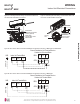

Table Of Contents

47
Installation Manual
Due to our policy of continuous product innovation, some specifications may change without notification.
©LG Electronics U.S.A., Inc., Englewood Cliffs, NJ. All rights reserved. “LG” is a registered trademark of LG Corp.
MAX
MULTI
F
MULTI
F
6. Route the power wiring / communications (connection) cable
through the bottom of the indoor unit (through a knockout panel)
to the terminal block.
7. Using a JIS screwdriver, connect the cable terminals to the
terminal block. Ensure wire color and terminal number of the
indoor unit matches those of the outdoor unit. Refer to the wiring
diagram on the inside of the cover.
8. Choice of the cable path out of the indoor unit and to the outdoor
unit depends on refrigerant piping / drain hose installation:
left side piping, following back of indoor unit; right side piping,
through the knockout hole; or rear piping.
• Each wire must be securely attached to the terminal block.
• Ground cable must be longer than the other wires.
• Secure the cable onto the control board using a cable tie.
• Use a conduit to protect the cable / refrigerant piping from the indoor unit to the outdoor unit.
Cable Installation When Piping is on the Left Side:
• Insert the communication / connection (power) cable through the bottom of the indoor unit.
• Connect the terminals to the terminal block.
• Secure the cable onto the terminal block with the cable retainer.
• Secure the refrigerant piping, drain hose, and communication / connection (power) cable together using cable ties and conduit, or by the
bundling method.
3RVLWLRQWKHGUDLQKRVHDWWKHERWWRP3RVLWLRQLQJWKHGUDLQKRVHDWWKHWRSRIWKHEXQGOHFDQFDXVHFRQGHQVDWHWRRYHUÀRZIURPWKHGUDLQSDQLQWKH
inside of the indoor unit.
Cable Installation When Piping is on the Right Side:
• Connect the terminals to the terminal block.
• Secure the cable onto the terminal block with the cable retainer.
• Secure the refrigerant piping, drain hose, and communication / connection (power) cable together using cable ties and conduit, or by the
bundling method.
• Position the drain hose at the bottom. Positioning the drain hose at the top of the bundle can cause condensate to overflow from the drain
pan in the inside of the indoor unit.
• For more information on conduits or the bundling method, see the Refrigerant Piping Connection section.
9. Reattach the control cover using the screw.
Figure 74: Indoor Unit
Knockout.
Figure 75: Indoor Unit Terminal Block
with Ground Cable (Example Only).
WIRING
,QGRRU8QLW(OHFWULFDO&RQQHFWLRQV