
LMN248HVT Installation Guide


35
Installation Manual
Due to our policy of continuous product innovation, some specifications may change without notification.
©LG Electronics U.S.A., Inc., Englewood Cliffs, NJ. All rights reserved. “LG” is a registered trademark of LG Corp.
MA
X
MUL
TI
F
MUL
TI
F
Note:
Follow locals codes when selecting EPDM insulation wall thickness. Thickness in Table 26 is based on heat conductivity of 0.61 Btu/in/h/ft2/°F.
Table 26: Insulation Guidelines for Typical and Special Circumstances.
Classication
Air-conditioned location Non-air conditioned location
1. Typical location 2. Special location 3. Typical location 4. Special location
Liquid pipe
ø1/4 inches
1/2 inches 1/2 inches 1/2 inches 1/2 inches
ø3/8 inches
≥ø1/2 inches 1/2 inches 1/2 inches 1/2 inches 1/2 inches
Vapor pipe
ø3/8 inches
1/2 inches 3/4 inches 3/4 inches 1 inch
ø1/2 inches
ø5/8 inches
ø3/4 inches
1. Air-conditioned, Typical location
• When piping passes through an indoor area where the indoor unit operates, such as an apartment, classroom, ofce, mall, hospital, etc.
2. Air-conditioned, Special location
• When the location is air conditioned, but has severe temp/humidity difference due to high ceilings, such as a church, auditorium, theater, etc.
• When the location is air conditioned, but internal temperature/humidity are high, such as a bathroom, swimming pool, locker room, etc.
3. Non-air conditioned, Typical location
• When piping passes through an indoor area where the indoor unit does not operate, such as a hallway, dormitory, or school, etc.
4. Non-air conditioned, Special location (when both conditions listed below are present)
• When piping passes through an indoor area that is not conditioned
• When the humidity is high and there is no air ow in the location where the piping is installed
Piping Insulation
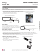
PIPING CONNECTIONS
Connecting the Indoor Unit Piping to the Field-Installed Piping
Note:
If the drain hose is routed inside a room,
add insulation to prevent condensation
from forming.
1. Center align the indoor unit piping (refrigerant and drain) and the
field-installed piping, then hand tighten the flare nut.
2. Tighten the flare nut with a torque wrench.
3. Attach the drain tube piping to the
indoor unit drain hose as shown.
Indoor unit piping
Flare nut Field-installed
piping
Spanner
Field-installed
piping
Flare nut
Torque
wrench
Figure 42: Indoor Unit to Field-Installed Piping Connection.
Narrow tape
Adhesive
Drain extension
Indoor unit
drain hose
Figure 43: Extending the Drain Hose.
Refrigerant Piping System Insulation
All refrigerant piping including Y-branch connections, field-provided isolation ball valves, service valves, and elbows must be completely
insulated using closed cell pipe insulation (up to the indoor unit piping connections). To prevent heat loss/heat gain through the refrigerant
piping, all refrigerant piping including liquid lines and vapor lines must be insulated separately. Insulation must be a minimum 1/2″ thick, and
thickness may need to be increased based on ambient conditions and local codes. Table 26 lists recommended minimum wall thickness
requirements for Ethylene Propylene Diene Methylene (EPDM) insulation.
Inside the outdoor unit, maximum pipe temperature is 248°F and minimum pipe temperature is -40°F. For field insulation of refrigerant piping
between outdoor units and indoor units, consider the following pipe temperature ranges for an operating heat pump system:
• Heating mode refrigerant temperature ranges: Liquid 75-118°F; High Pressure Vapor 95-220°F
• Cooling mode refrigerant temperature ranges: Liquid 75-118°F; Low Pressure Vapor 40-90°F