
Multi F Outdoor Condenser Installation Manual


71
Electrical System Installation
Due to our policy of continuous product innovation, some specifications may change without notification.
©LG Electronics U.S.A., Inc., Englewood Cliffs, NJ. All rights reserved. “LG” is a registered trademark of LG Corp.
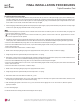
Figure 89: Detailed Diagrams of Outdoor Unit PCB Terminal Connections.
ELECTRICAL
,QVWDOODWLRQ
Indoor Unit Terminal Block
A Unit
Indoor Unit Terminal Block
B Unit
Indoor Unit Terminal Block
C Unit
Indoor Unit Terminal Block
D Unit
Indoor Unit Terminal Block
E Unit
Indoor Unit Terminal Block
F Unit
Indoor Unit Terminal Block
G Unit
Indoor Unit Terminal Block
H Unit
Multi F LMU18CHV Multi F LMU24CHV
Multi F LMU30CHV and LMU36CHV
Multi F MAX LMU480HV and LMU540HV
BD Unit (A)
BD Unit (A )
A Room B Room C Room D Room A Room B Room C Room D Room
BD Unit (B )
BD Unit (B)
1(L1) 2(L2) 3(A) 1(L1) 2(L2) 3(B) L1 L2
L(L1) N(L2) S L(L1) N(L2) S
1(L1) 2(L2) 3
L(L1) N(L2) S
1(L1) 2(L2) 3
L(L1) N(L2) S
1(L1) 2(L2) 3
L(L1) N(L2) S
1(L1) 2(L2) 3
L(L1) N(L2) S
1(L1) 2(L2) 3
L(L1) N(L2) S
1(L1) 2(L2) 3
L(L1) N(L2) S
1(L1) 2(L2) 3
L(L1) N(L2) S
1(L1) 2(L2) 3
L(L1) N(L2) S
Indoor Unit Terminal Block
A Unit
Indoor Unit Terminal Block
B Unit
Indoor Unit Terminal Block
C Unit
Indoor Unit Terminal Block
D Unit
Indoor Unit Terminal Block
E Unit
Indoor Unit Terminal Block
F Unit
Indoor Unit Terminal Block
G Unit
Indoor Unit Terminal Block
H Unit
Multi F MAX LMU600HV
To BD Units A and B
BD Unit (A )
A Room B Room C Room D Room A Room B Room C Room D Room
BD Unit (B )
1(L1) 2(L2) 3(A) 3(B) L1 L2
L(L1) N(L2) S L(L1) N(L2) S
1(L1) 2(L2) 3
L(L1) N(L2) S
1(L1) 2(L2) 3
L(L1) N(L2) S
1(L1) 2(L2) 3
L(L1) N(L2) S
1(L1) 2(L2) 3
L(L1) N(L2) S
1(L1) 2(L2) 3
L(L1) N(L2) S
1(L1) 2(L2) 3
L(L1) N(L2) S
1(L1) 2(L2) 3
L(L1) N(L2) S
1(L1) 2(L2) 3
L(L1) N(L2) S