
Ceiling Cassette Installation Manual

4
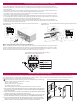
Connecting the Drain Pipe
Condensate Drain Pipe
All cassette indoor units have a factory-mounted condensate pump that
runs continuously while the unit is in cooling mode. The pump has an
internal high-level float switch that stops the unit if the water level in the
pan rises too high.
All cassette indoor units have a flexible drain hose kit and one or two
clamps. The hose can be used to connect the condensate pipe to the con-
densate pump connection.
• Indoor units DO NOT come with check valves or a backflow prevention
device. If check valves are needed, they must be field supplied.
• The maximum lift of all condensate pumps is 27 in.
• Measure lift distance from the bottom surface of the indoor unit, NOT
from the condensate pipe connection.
• Slope all horizontal condensate pipe segments a minimum of 1/4 inch
per foot away from the indoor unit.
• Ceiling cassette indoor units do not have a gravity condensate pipe con-
nection. There is a service drain plug on the bottom of each unit under
the decorative panel. This drain plug is intended as a service feature and
is not to be used as a permanent gravity drain connection.
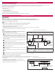
1/50~1/100
slope
Hanger distance
3.3~4.9 feet
Hanger Bracket
Flexible drain hose
Insulation
Metal
clamp
Max.
11-13/16 inches
PVC Piping
PVC Elbow
Drain pump
Max.
27 in. lift
Typical Indoor Unit Drain Pump to Drain Piping System
Configuration
Connecting Communication and Power Wiring
Connecting Communication and Power Wiring
Indoor unit installation best practices are to connect control wiring (low voltage) and then connect power wiring (high voltage). Do not apply power
to the indoor unit or any system component until authorized to do so by the system commissioning agent.
DANGER
High voltage electricity is required to operate this system. Adhere to National Electrical Codes and these instructions when wiring.
Improper connections and inadequate grounding can cause accidental injury or death.
Always ground the unit following local, state, and National Electrical Codes.
Improper connections and inadequate grounding can cause accidental injury or death.
Properly size all circuit breakers or fuses.
There is risk of re, electric shock, explosion, physical injury or death.
WARNING
The information contained in this manual is intended for use by a trained electrician familiar with applicable local codes and the U.S.
National Electric Code (NEC), and who is equipped with the proper tools and test instruments.
Failure to carefully read and follow all instructions in this manual can result in personal injury or death.
Connect the indoor unit input power cable but do not apply power to the indoor unit until authorized to do so by the system commis-
sioning agent.
Inappropriate power connection can result in personal injury or death.
Refer to local, state, and federal codes, and use power wires of sufcient current capacity and rating.
Wires that are too small may generate heat and cause a re, resulting in physical injury or death.
Properly tighten all power connections.
Loose wiring may overheat at connection points, causing a re, physical injury or death.
Don’ts
• Never use wire caps and never splice communications cables.
• Star and Wye communications cable configurations are not acceptable.
• Never connect zone controllers or other central control products such as AC Smart, PDI, or LG building management system gateway
products to the IDU/ODU communications cable.
Multi V Indoor Unit Wiring Configuration
Multi V IDUs require separate power and communication cables. The IDU
requires single-phase, 208-230 volt facility power. Be sure the powier
cables meet applicable local and national codes.
The field-supplied communications cable from the outdoor unit must
be minimum 18-2, stranded and shielded. Polarity matters for commu-
nication cable. When connecting the communications cable conductors
at each Multi V system component, be careful the conductor connected
to the IDU(A) terminal on the outdoor unit is connected to the A/3(A)
terminal at each indoor unit. The conductor connected to the IDU(B)
terminal on the outdoor unit must be connected to the B/4(B) terminals
at each indoor unit. Cross connecting the A/3(A) and B/4(B) terminals
will cause communications errors and system malfunction. Communica-
tion cables must be connected in a daisy chain configuration.
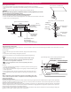
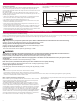
Typical Multi V 4-way Cassette IDU Power Wiring and Communications
Cable Terminals
Lock nut
Conduit
mounting
plate
Conduit
1(L1)
2(L2)
Power Supply
208/230V
1(L1) 2(L2) 3(A) 4(B)
Communication
Cable