
Ceiling Cassette Installation Manual

5
Connecting Communication and Power Wiring - continued
• Keep communications cables away from line voltage wiring, lighting ballasts, and other devices emitting
EMF energy. Maintain a minimum of two (2) inches between line voltage wires and communications or zone
controller cables.
• Field provide a minimum of 18-2 AWG, stranded and shielded, PVC or vinyl jacket communications wiring
between the indoor units, heat recovery boxes (if applicable), and outdoor units.
• The outdoor/indoor unit communications cable must be run between components in a daisy chain configu-
ration. Star or wye configurations are not allowed.
• Connect the communications cables to the A/3(A) and B/4(B) terminals at indoor units and/or heat recov-
ery units. Maintain polarity throughout the communications bus. Be sure A/3(A) terminals are connected to
A/3(A) terminals and B/4(B) terminals are connected to B/4(B) terminals.
• Connect the shields of the communications cable segments together at each indoor unit. Insulate each
shield connection to prevent electrical contact with the IDU. Ground the shield of the communications cable
at one end only, at the master outdoor unit.
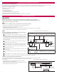
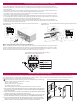
Multi F and Single Zone Indoor Unit Wiring Configuration
Multi F and Single Zone IDUs have a single cable from the outdoor unit that supplies both power and commu-
nication. This field-supplied cable must be minimum 18-4 stranded and shielded. Be sure the power conduc-
tors are connected to the line power terminals of the IDU. Be sure the communication conductor is connect-
ed to the communication terminal of the IDU and ground is connected to ground.
Power Supply
(208/230V)
L(L1) L(L2) 3
L(L1)
L(L2)
3
Communications
Ground
Typical Multi F and Single Zone IDU Power Wiring
and Communications Cable Terminals
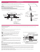
Optional Wired Wall Controller Installation
Since the room temperature sensor is inside the remote controller, to maintain proper space temperature install the remote controller in a
place away from direct sunlight, high humidity, and direct supply of hot or cold air. Install the remote controller about 5 ft above the floor in
an area with good air circulation and an average temperature.
Do not install the remote controller where it can be affected by the following:
• Drafts or dead spots behind doors and in corners
• Hot or cold air from ducts
• Radiant heat from sun or appliances
• Concealed pipes and chimneys
• Uncontrolled areas such as an outside wall behind the remote controller
1. Pull communications cable between the zone controller handy box (if used) and
the indoor unit. Use field supplied 22-3 twisted, stranded and unshielded cable
or LG supplied cable.
2. Store a minimal amount of cable in the handy box. Any additional cable should be
coiled and stored near the indoor unit control panel.
3. If using LG cable and additional cable length is needed, order a thirty-three (33)
foot LG Wired Remote Group Control Extension cable (Model No. PZCWRC1).
4. If using LG supplied cable and the cable between the zone controller and the
indoor unit is too long, do not cut the cable and shorten. Coil any spare commu-
nications cable, tie-wrap it, and leave it next to the indoor unit location.
5ft
no
no
no
yes
Remote Controller
TEMP
Remote Controller
TEMP
Rem
ote Controller
TEMP
Typical Wired Remote Controller Installation
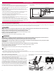
Lock nut
Conduit
1(L1) 2(L2)
3(A)
4(B)
Power Supply
High Voltage
(208/230V)
Communications
Typical Multi V 2-way Cassette IDU Power Wiring and Communications
Cable Terminals
1(L1) 2(L2)
3(A)
4(B)
Power Supply
High Voltage
(208/230V)
Communications
Lock nut
Conduit
mounting
plate
Conduit
Typical Multi V 1-way Cassette IDU Power Wiring and Communications
Cable Terminals