
LMN078HVT Installation Guide


31
Installation Manual
Due to our policy of continuous product innovation, some specifications may change without notification.
©LG Electronics U.S.A., Inc., Englewood Cliffs, NJ. All rights reserved. “LG” is a registered trademark of LG Corp.
MA
X
MUL
TI
F
MUL
TI
F
• Do not allow the refrigerant to leak during brazing; if refrigerant combusts, it generates a toxic gas which can cause physical injury or death.
• Do not braze in an enclosed location, and always test for gas leaks before/after brazing. Gas leaks can cause physical injury or death.
• After brazing, check for refrigerant gas leaks. Refrigerant gas leaks can cause physical injury or death.
• When selecting flare fittings, always use a 45° fitting rated for use with high pressure refrigerant R410A. Failure to do so may result in
refrigerant leaks which in turn could result in personal injuries or death from oxygen depletion. Selected fittings must also comply with local,
state, or federal standards.
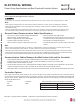
Creating a Flare Fitting
Note:
One of the main causes of refrigerant leaks is defective ared connections. Be sure to properly form the are connections.
1. Cut the pipe to length.
• Measure the distance between the indoor unit and the
outdoor unit.
• Cut the pipes a little longer than measured distance.
• Cut the cable 4.9 ft longer than the pipe length.
2A. Remove the burrs.
• Completely remove all burrs from pipe ends.
• When removing burrs, point the end of the copper pipe
down to avoid introducing foreign materials in the pipe.
2B. Slide the flare nut onto the copper tube.
3. Flaring the pipe end.
• Use the proper size aring tool to nish ared connections
as shown.
• Refer to the diagram in step 3 of Figure 35 and the dimen-
sions in Table 20 for positioning the pipe in the aring tool.
• ALWAYS create a 45° are when working with R410A. See
Warning on this page.
4. Carefully inspect the flared pipe end.
• Compare the are with the illustration in step 4 of Figure 35.
• If the are is defective, cut it off and re-do procedure.
• If are looks good, blow clean the pipe with dry nitrogen.
Pipe Outside
Diameter (inch)
“A” Measurement
(inch)
1/4 0.04 – 0.5
3/8 0.06 – 0.7
1/2 0.06 – 0.7
5/8 0.06 – 0.7
3/4 0.07 – 0.8
Table 20: Flare “A” Measurement
Piping Preparation
Note:
1. If piping becomes kinked due to excessive bending, do not use the pipe.
2. Braze the pipes to the service valve pipe stub of the outdoor unit.
Figure 35: Creating a Flare Fitting
Copper
tube
90°
Slanted Uneven Rough
Pipe
Reamer
Point
down
Flare nut
Copper
tube
Bar
Copper pipe
Clamp handle
Red arrow
Cone
Yoke
Handle
Bar
"A"
Slanted
Inside is shiny with no scratches
Smooth
Even length
Damaged
surface
Cracked Uneven
thickness
Incorrect Flares
1.
2A. 2B.
3.
4.
PIPING CONNECTIONS
Piping Preparation