
LMU540HV Installation Guide


48
MULTI F / MULTI F MAX Outdoor Unit Installation Manual
Due to our policy of continuous product innovation, some specifications may change without notification.
©LG Electronics U.S.A., Inc., Englewood Cliffs, NJ. All rights reserved. “LG” is a registered trademark of LG Corp.
MULTI
F
MAX
MULTI
F
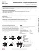
Surface of
Indoor Unit Casing
Field-Provided
Pipe Insulation
Figure 60: Typical Pipe Insulation, Power Wire and
Communications Cable Arrangement
Figure 61: Typical Insulation Butt-
Joint at Indoor Unit Casing
Figure 62: Typical Refrigerant
Flare Fitting Insulation Detail
•
Do not insulate gas and liquid pipes together as this
FDQUHVXOWLQSLSHOHDNDJHDQGPDOIXQFWLRQGXHWRH[WUHPH
temperature fluctuations.
• Be sure to fully insulate the piping connections.
Refrigerant Piping System Insulation
All refrigerant piping from the outdoor unit to the indoor units / BD units (Multi F MAX systems only) must be insulated correctly for safety and
usage. Y-branch connections, refrigerant piping, field-provided isolation ball valves (if present), service valves, and elbows must be properly
and completely insulated using closed cell pipe insulation (up to the indoor unit piping connections). To prevent heat loss / heat gain through
the refrigerant piping, all refrigerant piping including liquid lines and vapor lines shall be insulated separately. Insulation shall be a minimum
ƎWKLFNDQGWKLFNQHVVPD\QHHGWREHLQFUHDVHGEDVHGRQDPELHQWFRQGLWLRQVDQGORFDOFRGHV7DEOHEHORZOLVWVPLQLPXPZDOOWKLFNQHVV
requirements for Ethylene Propylene Diene Methylene (EPDM) insulation.
,QVLGHWKHRXWGRRUXQLWPD[LPXPSLSHWHPSHUDWXUHLV)DQGPLQLPXPSLSHWHPSHUDWXUHLV))RUILHOGLQVXODWLRQRIUHIULJHUDQWSLSLQJ
between outdoor units and indoor units, consider the following pipe temperature ranges for an operating heat pump system:
• +HDWLQJPRGHUHIULJHUDQWWHPSHUDWXUHUDQJHV/LTXLG)+LJK3UHVVXUH9DSRU)
• &RROLQJPRGHUHIULJHUDQWWHPSHUDWXUHUDQJHV/LTXLG)/RZ3UHVVXUH9DSRU)
Vapor Line
Liquid Line
Min. 18 Gauge
Cable
Power/Communication
Pi
p
e Sleeve
Insulation Material
Insulation
Material
Refrigerant Piping Insulation
Minimum Refrigerant Pipe Ethylene Propylene Diene Methylene (EPDM) Insulation Wall Thickness Requirements
Follow locals codes when selecting EPDM insulation wall thickness.
&ODVVLÀFDWLRQ
Air-conditioned location Non-air conditioned location
1. Typical location 2. Special location 3. Typical location 4. Special location
Liquid pipe
ø1/4 inch
1/2 inch 1/2 inch 1/2 inch 1/2 inch
ø3/8 inch
¡LQFK 1/2 inch 1/2 inch 1/2 inch 1/2 inch
Vapor pipe
ø3/8 inch
1/2 inch
3/4 inch 3/4 inch
1 inch
ø1/2 inch
ø5/8 inch
ø3/4 inch
ø7/8 inch
ø1 inch
ø1-1/8 inches
3/4 inch
ø1-1/4 inches
1 inch 1 inch
ø1-3/8 inches
ø1-1/2 inches
ø1-3/4 inches
Table 37: Insulation Guidelines for Typical and Special Circumstances
REFRIGERANT PIPING PREPARATION