
Engineering Manual


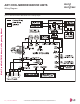

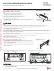
Table Of Contents
- Convergence of Technology, Innovation, Flexibility, & Style
- Unit Nomenclature
- Outdoor Unit Overview
- Indoor Unit Overview
- Controls and Options Overview
- Art Cool Mirror Indoor Units
- General Data / Specifications
- Dimensions
- Cooling Capacity Table
- Heating Capacity Table
- Acoustic Data
- Air Velocity and Temperature Distribution
- Refrigerant Flow Diagram
- Wiring Diagram
- Factory Supplied Parts and Materials
- Installation and Best Layout Practices
- Art Cool Gallery Indoor Units
- General Data / Specifications
- Dimensions
- Cooling Capacity Table
- Heating Capacity Table
- Acoustic Data
- Air Velocity and Temperature Distribution
- Refrigerant Flow Diagram
- Wiring Diagram
- Factory Supplied Parts and Materials
- Installation and Best Layout Practices
- Standard Wall-Mounted Indoor Units
- General Data / Specifications
- Dimensions
- Cooling Capacity Table
- Heating Capacity Table
- Acoustic Data
- Air Velocity and Temperature Distribution
- Refrigerant Flow Diagram
- Wiring Diagram
- Factory Supplied Parts and Materials
- Installation and Best Layout Practices
- Duct (Low Static) Indoor Units
- General Data / Specifications
- Dimensions
- Cooling Capacity Table
- Heating Capacity Table
- External Static Pressure
- Acoustic Data
- Refrigerant Flow Diagrams
- Wiring Diagram
- Factory Supplied Parts and Materials
- Installation and Best Layout Practices
- Duct (High Static) Indoor Units
- General Data / Specifications
- Dimensions
- Cooling Capacity Table
- Heating Capacity Table
- External Static Pressure / Acoustic Data
- Refrigerant Flow Diagrams
- Wiring Diagrams
- Factory Supplied Parts and Materials / Installation
- Installation and Best Layout Practices
- Four-Way Ceiling Cassette Indoor Units
- General Data / Specifications
- Dimensions
- Dimensions
- Cooling Capacity Table
- Heating Capacity Table
- Acoustic Data
- Air Velocity and Temperature Distribution
- Refrigerant Flow Diagram
- Wiring Diagram
- Factory Supplied Parts and Materials
- Installation and Best Layout Practices
- Vertical-Horizontal Indoor Units
- General Data / Specifications
- Dimensions
- Cooling Capacity Table
- Heating Capacity Table
- External Static Pressure
- Acoustic Data
- Refrigerant Flow Diagram
- Wiring Diagram
- Factory Supplied Parts and Materials
- Installation and Best Layout Practices
- Equipment Selection Procedure
- Building Ventilation Design Guide
- Placement Considerations
- Refrigerant Piping Design
- Design Guideline Summary
- Creating a Balanced System / Manual Layout Procedure
- LG Engineered Multi F MAX Y-Branch Kit
- Refrigerant Charge
- Installation & Layout Best Practices
- Refrigerant Piping System Layout
- Piping Insulation
- Condensate Drain Piping
- Y-Branch Kit
- Wiring Connections
- Power Wiring (208-230V) and Communications Cable Details
- Indoor Unit Group Control
- Acronyms

Selecting the Best Location
Do’s
• Place the unit where air circulation will not be blocked.
• Place the unit where drainage can be obtained easily.
• Place the unit where noise prevention is taken into consideration.
• Ensure there is sufficient space from the ceiling and floor.
• Ensure there is sufficient maintenance space.
• Locate the indoor unit in a location where it can be easily connected to the outdoor unit /
branch distribution unit.
Don’ts
• The unit should not be installed near a heat or steam source, or where considerable amounts of oil, iron powder, or flour are used.
• The unit should not be installed where sulfuric acid and flammable or corrosive gases are generated, vented into, or stored.
• Avoid installing the unit near high-frequency generators.
• Do not install the unit near a doorway.
The unit may be damaged, may malfunction, and / or will not operate as designed if installed in any of the conditions listed.
>4-11/16 inches
>4 inches
Recommended height
>6-1/2 feet from floor
>4 inches
Figure 12:Minimum Clearance Requirements.
Mounting the Installation Plate
The mounting wall should be strong and solid enough to protect the unit from vibration.
• Mount the installation plate on the wall using the Type “A” screws. If mounting the unit on
concrete, consider using anchor bolts.
• Always mount the installation plate horizontally. Measure the wall and mark the centerline
using thread and a level.
Figure 13:Installation Plate—
Side View.
Installation Plate
Frame
Hook
Type "A" Screws
Ø2-3/4 inches
Ø2-3/4
inches
5-1/4 inches
3-3/4 inches
Right rear piping
Left rear piping
Installation Plate
Place a level on raised tab
Unit Outline
8-17/32 inches
6-7/8 inches
Figure 14:Installation Plate for LMAN097HVT and LMAN127HVT Units. Figure 15:Installation Plate for LMAN187HVT Units.
Ø2-3/4 inches
Ø2-3/4 inches
2-23/32 inches
2-7/32 inches
Right rear
piping
Left rear
piping
Installation Plate
Measuring Tape
Measuring Tape Hanger
Place a level on raised tab
Unit Outline
8-5/32 inches
4-1/8 inches
18-1/8 inches 22-7/16 inches
If the unit is installed near a body of water, certain components are at risk of being corroded. Appropriate anti-corrosion methods should be
taken for the unit and all components.
ART COOL MIRROR INDOOR UNITS
Installation and Best Layout Practices
Installing in an Area Exposed to Unconditioned Air
In some installation applications, areas(floors, walls) in some rooms may be exposed to unconditioned air (room may be above or next to an
unheated garage or storeroom). To countermeasure:
• Verify that carpet is or will be installed (carpet may increase the temperature by three degrees).
• Add insulation between the floor joists.
• Install radiant heat or another type of heating system to the floor.
Due to our policy of continuous product innovation, some specications may change without notication.
©LG Electronics U.S.A., Inc., Englewood Cliffs, NJ. All rights reserved. “LG” is a registered trademark of LG Corp.
30 | ART COOL MIRROR
Multi F and Multi F MAX Indoor Unit Engineering Manual
MULTI
F
MAX
MULTI
F