
Indoor Unit Installation Guide


23
Installation Manual
Due to our policy of continuous product innovation, some specifications may change without notification.
©LG Electronics U.S.A., Inc., Englewood Cliffs, NJ. All rights reserved. “LG” is a registered trademark of LG Corp.
MA
X
MUL
TI
F
MUL
TI
F
Refrigerant Piping
GENERAL INSTALLATION GUIDELINES
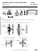
The LG supplied Y-Branch Kit PMBL5620 MUST be used when two branch distribution units are connected to one Multi F MAX system.
Field-supplied fittings are not permitted. Each Y-Branch kit comes with two (2) Y-branches (one for the liquid line and one for the vapor line)
and insulation covers.
Y-branches may be installed in horizontal or vertical configurations. When installed vertically, position the Y-branch so the straight-through
leg is ±3° of plumb. When installed horizontally, position the Y-branch so the take-off leg is level and shares the same horizontal plane as the
straight-through leg ±5° rotation.
Y-branches should always be installed with the single port facing the outdoor unit and the two-port end facing the branch distribution units.
Do not install Y-branches backwards as refrigerant flow cannot make U-turns. The Y-branch kit must be located at least three (3) feet from
the outdoor unit. Provide a minimum of 20 inches between a Y-branch and the branch distribution unit.
Figure 14: Y-Branch Port Identication and Dimensions.
Figure 15: Y-branch Horizontal Installation Alignment.
Multi F MAX Y-Branch Kit PMBL5620
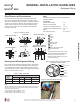
Y-Branch Kit Insulation
Each Y-branch kit comes with clam-shell type peel-and-
stick insulation jackets molded to fit the Y-branch fittings—
one for the liquid line, one for the vapor line.
Figure 16: Y-branch Vertical Installation Alignment.
Viewed from A in direction of arrow
Horizontal
plane
Within ±5
°
A
Vertical Up Configuration
Within ± 3°Within ± 3°
Vertical Down Configuration
Material
Polyolefin Foam
UL94 Flame Classication
HF-1
Density
1.84 lbs./ft.
3
Thermal Conductivity
.0208 Btu/h/ft. ºR
Thickness
1/2 inch
Liquid and Gas
Pipe Joints
Y-Branch Kit Insulation
Insulation for
Field-Installed Piping
Field-Supplied Insulation Tape
Table 11: Insulation Jacket Properties.
Figure 17: Y-Branch Insulation Jacket Diagram.
Model
Y-Branch
Type
Port Identier (inch)
1 2 3
PMBL5620
Liquid Ø3/8 Ø3/8 Ø3/8
Vapor Ø3/4 Ø3/4 Ø3/4
Y-Branch
Type
Dimensions (inch)
X Y
Liquid 13.80 3.24
Vapor 12.48 3.02
Table 12: Multi F MAX Y-Branch Connection Diameters.
A
B
X
Y
1
2
3
A = To Outdoor Unit
B = To Branch Distribution Unit
1
2
3