
LMCN078HV Engineering Manual


Horizontal Installation
• Units will be installed in horizontal left or horizontal right con-
figuration. Horizontal left is the factory default configuration. For
horizontal right, the unit must be field converted. The horizontal
right conversion requires removing the internal drain pan from the
left side of the unit and reinstalling on the right side. No conver-
sion kit is required. Refer to the installation manual for details.
• Units must be installed so that the access panels face to the side,
not facing up or down.
• Installation must be in accordance with all relevant building
codes, which will necessitate the installation of an external con-
densate pan (position the unit in or above the external conden-
sate pan).
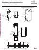
• If the units are going to be suspended, use angled steel support
brackets with threaded rods to provide support from the bottom.
The brackets / threaded rods must be comparatively bigger /
longer than the unit, and each must be centered on the part of
the frame it supports.
• If the unit will not be suspended, use angled steel support
brackets, but also add vibration isolators (field supplied) to avoid
sound transmission. If necessary, provide the installing contractor
with an illustration of where the vibration isolator must be added
and how it must be positioned.
• Unit must be positioned properly for plenum / duct installation.
• Plenum must be strong and secure enough to support the instal-
lation of adapter collars to accommodate duct work.
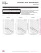
To ensure proper drainage for horizontal installations, unit must be
installed within ±1/8 inches level of the unit’s length and width.
Capacity
(Btu/h)
Dimensions (inches)
A B C
18,000 4 23 41-11/32
24,000 4 23 41-11/32
36,000 4 23 41-11/32
Figure 228: Typical Horizontal Left Installation.
Table 103: Bracket / Bolt Position Dimensions for Horizontal Left and
Horizontal Right Installation.
B
A
C
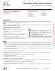
>1-1/2 inch x 1-1/2 inch Angle
Recommended length >26 inches
with a 2-inch clearance on both
sides of the unit
>3/8 inch Threaded Rod
Field-Supplied
Supply Air Duct
Field Supplied
Return Air Duct / Plenum
Suspension Bolt Locations
FOUR-WAY VAHU INDOOR UNITS
Installation and Best Layout Practices
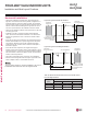
>1-1/2 inch x 1-1/2 inch Angle
Recommended length >26 inches
with a 2-inch clearance on both
sides of the unit
Suspension Bolt Locations
A
B
C
>3/8 inch Threaded Rod
Field Supplied
Return Air Duct / Plenum
Field-Supplied
Supply Air Duct
Figure 229: Typical Horizontal Right Installation.
Due to our policy of continuous product innovation, some specications may change without notication.
©LG Electronics U.S.A., Inc., Englewood Cliffs, NJ. All rights reserved. “LG” is a registered trademark of LG Corp.
178 | VERTICAL-HORIZONTAL
Multi F and Multi F MAX Indoor Unit Engineering Manual
MULTI
F
MAX
MULTI
F