
LMCN078HV Engineering Manual


Installing the Ducts
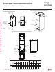
• Use more than ten (10) screws to securely attach the supply ducts to the
unit. To prevent air leaks, seal around the duct opening before the duct is
secure.
• To prevent vibration transmission, install flexible connectors between ducts
and the unit. The flexible connectors must be made of a heat-resistant
material at the discharge connection if an electric heater is installed.
• Duct work must be insulated and covered with vapor barrier when routed
through unconditioned spaces. Include enough insulation to prevent
condensate from forming on the ducts.
• It will be necessary to add internal acoustical insulation lining for a metal
duct system if it does not include a 90° elbow and ten (10) feet between the
main duct and the first branch.
• Fibrous glass ducts could be used as a substitute if built and installed in accordance with the most recent edition of the Sheet Metal and
Air-Conditioning Contractors’ National Associate (SMACNA) standard.
• Also, fibrous duct work and acoustical insulation lining must also follow National Fire Protection Standard 90A or B as tested by UL
Standard 181 for Class 1 air ducts.
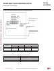
FOUR-WAY VAHU INDOOR UNITS
Installation and Best Layout Practices
>10 Screws
(M4*25L)
Figure 230:Securing the Ducts to the Unit.
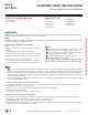
Installing the Drain System
General Specifications
• To prevent property damage, optimize drain system performance by installing both a primary and secondary drain line, and properly size
the condensate traps.
• The primary and secondary drain line must be trapped to allow proper drainage of condensate water. If the secondary drain line is not used,
it must be capped.
• Do not block the filter access panel when installing the condensate drain piping. Prime the primary and secondary condensate traps
after running both to the drain pan.
• If the unit is installed above an inhabited space, add a field-supplied external condensate pan that runs underneath the entire frame (to
prevent damage from overflow). The additional external condensate line must run from the unit to the external condensate pan.
• Drain all generated condensate from the external condensate pan to an appropriate area. Install a trap in the condensate lines as near to
the indoor unit coil as possible.
• For horizontal right operation, the drain pan must be removed from the interior left side of the unit and reinstalled on the right side.
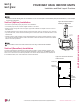
• All condensate must be drained from the exter-
nal condensate pan to some noticeable area.
• To prevent overflow, the outlet of each trap
must be positioned below its connection to the
condensate pan.
• All traps must be primed, insulated, and leak
tested if located above an inhabited space.
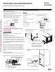
• Use a 3/4-inch PVC male pipe thread fitting at
the condensate pan connection. Tighten gently.
• Point the drain hose down for easier flow.
• Do not just use the pipe joint or PVC /
CPVC piping on the indoor unit drain line con-
nections. Use only Teflon tape.
• Design the drain system to plan for winter
operation (condensate line will freeze up if con-
densate does not properly drain away).
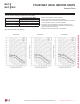
Figure 231: Typical Vertical Up/Down
Installation Drain System.
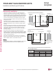
Figure 232: Typical Horizontal Left/Right
Installation Drain System.
Field-Supplied
Drain Pan
Drain Piping
Field-Supplied
Drain Pan
Drain Piping
VERTICAL-HORIZONTAL | 179
Vertical-Horizontal Air Handling Unit
Due to our policy of continuous product innovation, some specications may change without notication.
©LG Electronics U.S.A., Inc., Englewood Cliffs, NJ. All rights reserved. “LG” is a registered trademark of LG Corp.
MULTI
F
MAX
MULTI
F