
Multi F Four-Way Ceiling Cassette Service Manual

Part 5. Trouble Shooting
- 79 -
Copyright ©2014 LG Electronics. Inc. All right reserved.
Only for training and service purposes
LGE Internal Use Only
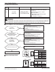
22
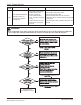
Max. C/T
Input Over Current(36k-
17A↑ 54k-29A↑)
1. Malfunction of Compressor
2. Blocking of Pipe
3. Low Voltage Input
4. Refrigerant, Pipe length, Blocked...
Display
code
Title Cause of error Check point & Normal condition
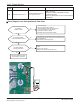
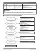
■ Error Diagnosis and Countermeasure Flow Chart
Is installation
condition normal?
No
Yes
Yes
Yes
Recheck power and installation condition
Yes
1. Check Pipe clogging/distortion
2. Check Covering (Indoor/Outdoor Unit)
3. Check EEV connector assemble condition/normal
operation
4. Check refrigerant pressure
→ Reassemble or manage if abnormality found
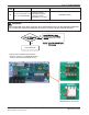
Is inverter PCB assembly
power connection normal?
No
Check connection between inverter PCB assembly and
bridge diode(misconnection, disconnection)
→ wiring again if abnormality found
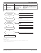
Yes
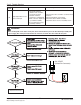
Is input voltage normal?
No
Check
L~N phase is 230V 15%
→ Check connection condition and wiring if power is
abnormal
Yes
Is inverter PCB assembly
normal?
No
Check inverter PCB assembly IPM normality
→ Replace inverter PCB assembly
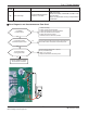
Are the resistance
Between each phase and
insulation resistance of Inverter
compressor normal?
No
1. Check resistance between each terminal of compressor
(0.438~0.628±7%)
2. Check insulation resistance between compressor
terminal and pipe (over 2MΩ)
→ Replace compressor if abnormality found
Is compressor
Wire connection
condition normal?
No
1. Check inverter PCB assembly U,V,W connector
connection condition
2. Check wire disconnection and wiring
3. Check compressor terminal connection condition
(bad contact)
→ Reassemble if abnormality found
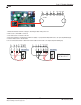
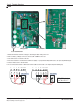
WARNING
Before checking PCB or each outdoor electric parts, wait for 3 minutes after the power is off. When measuring at standby state
of power supply, after checking the measurement mode of the meter, be careful of the short-circuits with other parts.