
Multi F Four-Way Ceiling Cassette Service Manual

Part 5. Trouble Shooting
- 92 -
Copyright ©2014 LG Electronics. Inc. All right reserved.
Only for training and service purposes
LGE Internal Use Only
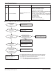
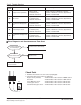
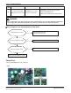
Check Point
1. Check the Input Voltage (L–N ➔ 230V±10%)
2. Check Input Voltage Sensor output voltage (2.5Vdc±10%)
Is Inverter PCB Normal?
No
Replace inverter PCB assembly
Is input voltage normal ?
No
Check L~N Voltage is 230V±15%
Yes
< Input Power Source Check Point >
Recheck power and
installation condition
Yes
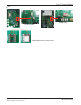
■ Error Diagnosis and Countermeasure Flow Chart
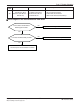
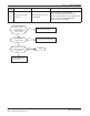
40
C/T
Sensor Error
• Initial current error
•
Malfunction of current detection circuit.
(Open / Short)
•
Check CT Sensor output voltage :
2.5Vdc ±5%
Display
code
Title Cause of error Check point & Normal condition
WARNING
Before checking PCB or each outdoor electric parts, wait for 3 minutes after the power is off. When measuring at standby state
of power supply, after checking the measurement mode of the meter, be careful of the short-circuits with other parts.
■ Error Diagnosis and Countermeasure Flow Chart