
Multi F Installation Manual


38
MULTI F / MULTI F MAX Outdoor Unit Installation Manual
Due to our policy of continuous product innovation, some specifications may change without notification.
©LG Electronics U.S.A., Inc., Englewood Cliffs, NJ. All rights reserved. “LG” is a registered trademark of LG Corp.
MULTI
F
MAX
MULTI
F
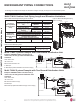
REFRIGERANT PIPING CONNECTIONS
Multi F MAX Outdoor Unit System Piping Connections
Branch Distribution to Indoor Unit Piping Connections
• Install indoor unit liquid and vapor refrigerant pipes (and connec-
tion wiring) to the appropriate branch distribution ports.
• Clearly note on the indoor unit’s refrigerant piping (liquid, vapor)
which branch distribution port it is connected to (A, B, C, D).
Outdoor Unit Piping Connections
LMU480HV, LMU540HV,
LMU600HV
Liquid Line Connection
(in., OD) x Qty.
3/8 x 1
Vapor Line Connection
(in., OD) x Qty.
3/4 x 1
Avoid Pipe Damage
• :KHQURXWLQJILHOGSURYLGHGSLSLQJDYRLGGDPDJLQJWKHRXWGRRUXQLWIURPH[FHVVLYHYLEUDWLRQ
• Properly insulate the liquid and gas lines separately up to the point of connection at the unit frame.
• See table below for Multi F MAX outdoor unit connection types.
Table 28: Outdoor Unit Piping Connections.
Table 29: Branch Distribution Unit Piping Connections.
Table 30: Indoor Unit Pipe Sizes.
Branch Distribution Unit PMBD3620 PMBD3630 PMBD3640 PMBD3641
Piping Connections to Outdoor Unit
Liquid (in., OD) x Qty. Ø3/8 x 1
Vapor (in., OD) x Qty. Ø3/4 x 1
Piping Connections to Indoor Units
Liquid (in., OD) x Qty. Ø1/4 x 2 Ø1/4 x 3 Ø1/4 x 4 Ø1/4 x 4
Vapor (in., OD) x Qty. Ø3/8 x 2 Ø3/8 x 3 Ø3/8 x 4 Ø3/8 x 3, Ø1/2 x 1
Table 31: Indoor Unit Piping Connections.
Connection sockets (included as a factory-supplied accessory with the indoor units) may need to be used when piping the indoor units to the
EUDQFKGLVWULEXWLRQXQLW,ID.LQGRRUXQLWLVLQFOXGHGWKHFRQQHFWLRQVRFNHWVDUHLQFOXGHGZLWKWKH%UDQFK'LVWULEXWLRQXQLW
Indoor Unit Capacity
Vapor (in., OD) Liquid (in., OD)
A B A B
18,000 Btu/h: Wall-
Mounted
ĺĺ
Ø5/8
ĺ
18,000 Btu/h: Low Static
Duct, Four-Way Cassette
ĺ N/A
24,000 Btu/h ĺ N/A
36,000 Btu/h ĺ ĺ
Connection Socket
A
B
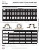
Figure 46: Branch Distribution Ports to Indoor Units.
ABC D
Figure 47: Connection Socket Diagram.
Indoor Unit
Capa c i t y
Vapor Line
Piping Size (in., OD)
Liquid Line
Piping Size (in., OD)
7,000 Btu/h
Ø3/8
Ø1/4
9,000 Btu/h
12,000 Btu/h
15,000 Btu/h
18,000 Btu/h
Ø1/2
24,000 Btu/h
36,000 Btu/h Ø5/8 Ø3/8
Table 32: Connection Socket Dimensions.
Indoor Unit Capacity
Vapor Line
Conn. (in., OD)
Liquid Line
Conn. (in., OD)
7,000 Btu/h
Ø3/8 Ø1/4
9,000 Btu/h
12,000 Btu/h
15,000 Btu/h
18,000 Btu/h: Wall-Mounted Ø5/8 Ø3/8
18,000 Btu/h: Low Static Duct,
Four-Way Cassette
Ø1/2 Ø1/4
24,000 Btu/h Ø1/2 Ø1/4
36,000 Btu/h Ø5/8 Ø3/8
Correctly route the piping so it does not make contact with mount-
LQJEROWV$OORZURRPIRU¿HOGLQVWDOODWLRQ