
Multi F Installation Manual


42
MULTI F / MULTI F MAX Outdoor Unit Installation Manual
Due to our policy of continuous product innovation, some specifications may change without notification.
©LG Electronics U.S.A., Inc., Englewood Cliffs, NJ. All rights reserved. “LG” is a registered trademark of LG Corp.
MULTI
F
MAX
MULTI
F
Leak Test and Vacuum Procedures
Before performing the test run, Multi F and Multi F MAX refrigerant piping and the piping connections to the outdoor unit, the indoor units, and
the BD units (Multi F MAX systems only) must be evacuated to remove any non-condensible gases and moisture that may be present in the
system, and checked for leaks. Air and moisture that is left in the piping can lead to undesirable results and can cause damage to the working
unit. It is important to go through a complete air purging cycle to be sure that the lines are cleared out. Note that this process may have to be
repeated should any air or moisture be found to remain in the piping. After air purging and evacuating the lines, be sure to take a leak test for
all piping and tubing. If any air and moisture remain in the refrigerant system:
1. Pressure in the system rises.
2. Operating current rises.
3. Cooling or heating efficiency drops.
4. Moisture in the refrigerant circuit may freeze and block capillary
tubing.
5. Water may corrode parts of the refrigeration system.
Before the Leak Test
1. Check that all refrigerant piping, the drain pipe, and power wiring / communications
cables are properly connected.
2. Remove the caps from both the gas and the liquid service valves on the outdoor
unit. Verify that both service valves are closed.
Pressure Gauge Hookup
3. Connect the manifold valve (which includes the pressure gauges), along with the dry
nitrogen gas cylinder, to the service valves using the charge hoses.
Use a manifold valve for leak testing. The high side manifold valve must always be kept
closed.
Leak Test Procedure
4. Pressurize the system to maximum 550 psig with the dry nitrogen gas.
8VHRIFRPEXVWLEOHJDVHVLQFOXGLQJR[\JHQPD\UHVXOWLQ¿UHRUH[SORVLRQUHVXOWLQJLQ
personal injury or death.
8VHRIFRPEXVWLEOHJDVHVLQFOXGLQJR[\JHQUXQVWKHULVNRI¿UHDQGH[SORVLRQUHVXOWLQJLQ
personal injury or death. Inert gas (nitrogen) should be used when checking leaks, cleaning
or repairs of pipes, etc.
• To avoid nitrogen entering the refrigerant system in a liquid state, the top of the cylinder must be higher than its bottom when the system is
pressurized.
• The cylinder should be used in a vertical standing position.
5. Close the cylinder valve when the gauge reading reaches 550 psig, and then test for leaks using the liquid soap method.
6. While running the nitrogen gas tank hookup, apply a soap water or a liquid neutral detergent to all indoor, BD, outdoor unit connection(s),
and all refrigerant piping joints with a soft brush. Also test for leaks at both of the gas and liquid side service valves.
Perform the leak test by pressurizing nitrogen gas to 550 psi on both the liquid and gas pipes. Test with the piping service valves closed. If the
pressure does not drop for twenty-four (24) hours, the system passes the test. If the pressure drops, there is a nitrogen leak in the system. Find the
leak, repair, and then test again.
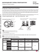
Leak Test
DANGER
Figure 54: Leak Test Diagram.
Charge Hose
Nitrogen Gas
Cylinder (with
cylinder upright)
Indoor Units
Outdoor Unit
Lo Hi
Manifold Valve
Pressure
Gauge
Appearances will vary depending on model.
REFRIGERANT PIPING PREPARATION
Leak Test