MULTI F MULTI F MAX CEILING CASSETTE INDOOR UNIT INSTALLATION MANUAL • LMCN077HV 7 kBtu • LCN097HV4 9 kBtu • LCN127HV4 12 kBtu • LMCN185HV 18 kBtu
PROPRIETARY DATA NOTICE This document, as well as all reports, illustrations, data, information, and other materials are the property of LG Electronics U.S.A., Inc., and are disclosed by LG Electronics U.S.A., Inc., only in confidence. Do not throw away, destroy, or lose this manual. Please read carefully and store in a safe place for future reference. Content familiarity required for proper installation.
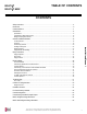
MULTI F MULTI F MAX TABLE OF CONTENTS CONTENTS Safety Instructions ������������������������������������������������������������������������������������������������������������������������������������������� 4 Introduction ������������������������������������������������������������������������������������������������������������������������������������������������������ 9 Unit Nomenclature ���������������������������������������������������������������������������������������������������������������������
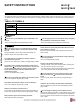
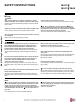
MULTI F MULTI F MAX SAFETY INSTRUCTIONS The instructions below must be followed to prevent product malfunction, property damage, injury or death to the user or other people. Incorrect operation due to ignoring any instructions will cause harm or damage. The level of seriousness is classified by the symbols described below. TABLE OF SYMBOLS DANGER This symbol indicates an imminently hazardous situation which, if not avoided, will result in death or serious injury.
MULTI F MULTI F MAX SAFETY INSTRUCTIONS Installation, continued If the air conditioner is installed in a small space, take measures to prevent the refrigerant concentration from exceeding safety limits in the event of a refrigerant leak. Consult the latest edition of ASHRAE (American Society of Heating, Refrigerating, and Air Conditioning Engineers) Standard 15. If the refrigerant leaks and safety limits are exceeded, it could result in personal injuries or death from oxygen depletion.
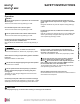
MULTI F MULTI F MAX SAFETY INSTRUCTIONS Wiring DANGER High voltage electricity is required to operate this system. Adhere to the NEC code and these instructions when wiring. Improper connections and inadequate grounding can cause accidental injury or death. Always ground the unit following local, state, and NEC codes. Multi F Ceiling Cassette Indoor Unit There is risk of fire, electric shock, and physical injury or death. Properly size all circuit breakers or fuses.
MULTI F MULTI F MAX SAFETY INSTRUCTIONS Operation DANGER Do not provide power to or operate the unit if it is flooded or submerged. There is risk of fire, electric shock, physical injury or death. Use inert (nitrogen) gas when performing leak tests or air purges. Do not use compressed air, oxygen, or flammable gases. Using these substances may cause fire, explosion, and physical injury or death. Use a dedicated power source for this system.
MULTI F MULTI F MAX SAFETY INSTRUCTIONS Operation, continued Note: Clean up the site after installation is finished, and check that no metal scraps, screws, or bits of wiring have been left inside or surrounding the unit. Multi F Ceiling Cassette Indoor Unit Do not use this equipment in mission critical or specialpurpose applications such as preserving foods, works of art, wine coolers or refrigeration. This equipment is designed to provide comfort cooling and heating. Oil, steam, sulfuric smoke, etc.
MULTI F MULTI F MAX INTRODUCTION Multi F and Multi F MAX Ceiling Cassette Units This manual describes how to install the LG Multi F and Multi F MAX (Multi Zone) Ceiling Cassette Indoor Units (IDU) for Multi F heat pump systems. Table 1 lists the available models. Refer to LG’s Multi F Indoor Unit Engineering Manual for complete detailed engineering data and selection procedures. Safety Safety of personnel is the primary concern during all procedures.
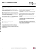
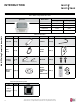
MULTI F MULTI F MAX INTRODUCTION Table 1: Multi F Ceiling Cassette Indoor Units. Typical Unit Nominal Capacity Model Number Cooling (Btu) Heating (Btu) LMCN077HV 7,000 8,100 LCN097HV4 9,000 10,400 LCN127HV4 12,000 13,800 LMCN185HV 18,000 20,800 Multi F Ceiling Cassette Indoor Unit Table 2: Included Items.
MULTI F MULTI F MAX UNIT NOMENCLATURE Multi F Multi-Zone Systems — Indoor Units L M CN 077 HV 4 L = LG Type: M = Multi-Zone A / S = Single Zone (Gen 4 Single Zone units also compatible with Multi Zone) Component: AN: Art Cool™ Wall-Mounted Indoor Unit Installation Manual N: Standard Wall-Mounted Indoor Unit CN: Four-Way Ceiling-Cassette Indoor Unit DN: Ceiling-Concealed Duct (Low Static) Indoor Unit HN: Ceiling-Concealed Duct (High Static) Indoor Unit VN: Vertical-Horizontal Air Handling Indoor Un
MULTI F MULTI F MAX GENERAL DATA R410A Refrigerant R410A refrigerant has a higher operating pressure in comparison to R22 refrigerant and, therefore, all piping system materials installed must have a higher resisting pressure than the materials traditionally used in R22 systems. R410A refrigerant is an azeotrope of R32 and R125, mixed at 50:50, so the ozone depletion potential (ODP) is 0. WARNING Do not place refrigerant cylinder in direct sunlight.
MULTI F MULTI F MAX GENERAL DATA Specifications Table 5: Multi F Multi Zone Ceiling Cassette Indoor Unit Specifications.
MULTI F MULTI F MAX GENERAL DATA Figure 2: Multi F Four-Way Ceiling-Cassette Indoor Unit Refrigerant Flow Diagram.
MULTI F MULTI F MAX GENERAL DATA Typical Multi F/Multi F Max Systems Major System Components A typical Multi F system consists of an outdoor unit (ODU), refrigerant piping, and two (2) to four (4) indoor units (IDUs). The ceiling cassette units described in this manual are one of the types of IDUs that can be connected to a Multi F system. A typical Multi F Max system consists of an ODU, refrigerant piping, one or two branch distribution units (BDU), and two (2) to eight (8) IDUs.
MULTI F MULTI F MAX GENERAL DATA Typical Multi F/Multi F Max Systems Typical Multi F MAX System with Two Branch Distribution Units ODU A Y-Branch IDU: Indoor Unit. A BD: Branch Distribution Unit(s). ΣB: Branch Piping (Branch Distribution Unit[s] to Indoor Unit[s]). IDU B IDU B IDU h4 ≤ 49.2 feet B A BDU IDU B B h1 ≤ 98.4 feet h2 ≤ 49.2 feet ΣA: Main Piping.
MULTI F MULTI F MAX GENERAL DATA Refrigerant Piping Requirements Field Supplied Refrigerant Piping Type ACR copper is the only approved refrigerant pipe material for use with LG Multi F air conditioning products. ACR rated tubing is the only type that ships with yellow caps. Approved tubing for use with Multi F products will be marked “R410 RATED” along the length of the tube. Tube wall thickness should meet local code requirements and be approved for a maximum operating pressure of 551 psi.
GENERAL INSTALLATION GUIDELINES Location Selection MULTI F MULTI F MAX DANGER To avoid the possibility of fire, do not install the unit in an area where combustible gas may generate, flow, stagnate, or leak. Installing the unit in an area containing combustible gas will cause serious bodily injury or death. Note: Before beginning installation, read the safety summary at the beginning of this manual.
MULTI F MULTI F MAX GENERAL INSTALLATION GUIDELINES Location Selection / Inspection Installing in an Area with High Humidity Levels If the environment is prone to humidity levels of 80% or more (near the ocean, lakes, etc.) or where steam could collect in the plenum: Figure 3: Installing in a Highly Humid Location. • Install additional insulation to the indoor unit (glass wool insulation >13/32 inches thick). • Install additional insulation to the refrigerant piping (insulation >13/16 inches thick).
MULTI F MULTI F MAX GENERAL INSTALLATION GUIDELINES Unpack and Inspect for Freight Damage, continued. 1. Before opening the shipping container, verify the correct unit is included as described in the note on the previous page. 2. Place the box on a solid surface right side up. 3. Cut the white reinforced nylon straps. 4. Open the box. 5. Remove any protective cardboard / Styrofoam® top sheets and place to the side. 6. The walls and top panels are not attached to the bottom of the box.
GENERAL INSTALLATION GUIDELINES Install Ceiling Cassette Figure 9: Installing the Hanging Bolt in the Ceiling. Ceiling Anchor Long nut or turnbuckle Suspension bolt Figure 10: Installation Diagram.
MULTI F MULTI F MAX GENERAL INSTALLATION GUIDELINES Installing Drain System Multi F Ceiling Cassette Indoor Unit Installing the Drain System Figure 12: Ceiling Cassette Indoor Unit Drain System. ≤11-13/16 inches PVC Elbow (Field Supplied) Maximum 27-9/16 inches • The unit uses a drain pump with a height of up to 27-9/16 inches to remove condensate from the indoor unit to the drainage system.
MULTI F MULTI F MAX GENERAL INSTALLATION GUIDELINES Insulating Drain Piping / Refrigerant Piping Insulating the Drain Piping Figure 17: Insulating the Drain Piping. • Drain piping insulation should be made of polyethylene foam with a minimum thickness of 7/16 inches. • Secure drain hose insulation at the drain port connection on the indoor unit so that no gaps exist. Insulation (Field Supplied) Drain Piping (Field Supplied) Indoor Unit Note: LG Electronics U.S.A.,Inc.
MULTI F MULTI F MAX GENERAL INSTALLATION GUIDELINES Refrigerant Piping Multi F MAX Y-Branch Kit PMBL5620 The LG supplied Y-Branch Kit PMBL5620 MUST be used when two branch distribution units are connected to one Multi F MAX system. Field-supplied fittings are not permitted. Each Y-branch kit comes with two (2) Y-branches (one for the liquid line and one for the vapor line) and insulation covers. Y-branches may be installed in horizontal or vertical configurations.
MULTI F MULTI F MAX GENERAL INSTALLATION GUIDELINES Refrigerant Piping Selecting Field-Supplied Copper Tubing Copper is the only approved refrigerant pipe material for use with Multi F products, and LG recommends seamless phosphorous deoxidized ACR type copper pipe, hard-drawn rigid type “K” or “L”, or annealed-tempered, copper pipe. • Drawn temper (rigid) ACR copper tubing is available in sizes 3/8 through 2-1/8 inches (ASTM B 280, clean, dry, and capped).
GENERAL INSTALLATION GUIDELINES Refrigerant Piping MULTI F MULTI F MAX No Pipe Size Substitutions Note: Use only the pipe size recommended by this installation manual. Using a different size is prohibited and may result in system malfunction or failure. Copper Expansion and Contraction Multi F Ceiling Cassette Indoor Unit Under normal operating conditions, the vapor pipe temperature of a Duct Free System can vary as much as 280°F.
MULTI F MULTI F MAX GENERAL INSTALLATION GUIDELINES Refrigerant Piping See table below for precalculated anticipated expansion for various pipe sizes and lengths of refrigerant tubing. To find the anticipated expansion value: 1. From the table below, find the row corresponding with the actual feet of the straight pipe segment. 2. Estimate the minimum and maximum temperature of the pipe. 3.
MULTI F MULTI F MAX GENERAL INSTALLATION GUIDELINES Refrigerant Piping Inserts and Pipe Supports Inserts An insert can be installed into a floor or beam before the concrete sets so that fittings such as ducts, pipes, or suspension bolts can be added at a later time. Decide where the inserts should be placed before support installation. Anti-vibration Material Insert Pipe Supports Figure 24: Installing an Insert Into a Concrete Beam.
MULTI F MULTI F MAX GENERAL INSTALLATION GUIDELINES Refrigerant Piping Examples of Supports Figure 29: U-Bolt Support with Insulation. Figure 31: Saddle-Type Support. Figure 30: O-Ring Support with Insulation. Bolt Insulation Support at Intervals Between 5 and 6-3/4 Feet Bolt 1.5t Plate PVC PVC Note: Do not compress the insulation with the saddle-type support. If the insulation is compressed, it may tear open and allow condensation to generate during product operation.
GENERAL INSTALLATION GUIDELINES Refrigerant Piping Note: Pipe Sleeves at Penetrations Pipe diameter plus insulation thickness determines wall penetration diameter. For example: Diameter of Gas Piping: 1/2" Diameter of Liquid Piping: 1/4" Thickness of Gas Piping Insulation: 0.4" x 2 Thickness of Liquid Piping Insulation: 0.4" x 2 Surplus: 0.8" Sleeve diameter (total): 3.
MULTI F MULTI F MAX GENERAL INSTALLATION GUIDELINES Piping Materials and Handling Piping Materials and Handling Figure 39: Keep Piping Capped While Storing. Pipes used for the refrigerant piping system must include the specified thickness, and the interior must be clean. While handling and storing, do not bend or damage the pipes, and take care not to contaminate the interior with dust, moisture, etc. See Table 21 for care of piping. Table 21: Three Principles of Refrigerant Piping.
MULTI F MULTI F MAX PIPING CONNECTIONS Piping Preparation Piping Preparation • Do not allow the refrigerant to leak during brazing; if refrigerant combusts, it generates a toxic gas which can cause physical injury or death. • Do not braze in an enclosed location, and always test for gas leaks before / after brazing. Gas leaks can cause physical injury or death. • After brazing, check for refrigerant gas leaks. Refrigerant gas leaks can cause physical injury or death.
MULTI F MULTI F MAX PIPING CONNECTIONS IDU to ODU Tightening the Flare Note: Do not use polyolyester (POE) or any other type of mineral oil as a thread lubricant. These lubricants are not compatible with PVE oil used in this system and create oil sludge leading to equipment damage and system malfunction. 1. 2. 3. 4. 5. When connecting the flare nuts, coat the flare (inside and outside) with polyvinyl ether (PVE) refrigeration oil only.
MULTI F MULTI F MAX PIPING CONNECTIONS IDU to ODU Multi F Outdoor Unit to Indoor Unit Piping Connections, continued. Figure 42: Connection Socket Diagram. Connection sockets (included as a factory-supplied accessory with the indoor units) may need to be used when piping the indoor units to the outdoor unit. Table 27: Connection Socket Dimensions. Indoor Unit Capacity Multi F Ceiling Cassette Indoor Unit 18,000 Btu/h A Vapor (in., OD) B Ø3/8 → Ø1/2 Flare to Outdoor Unit Liquid (in.
MULTI F MULTI F MAX PIPING CONNECTIONS IDU to ODU Multi F MAX Outdoor Unit System Piping Connections, continued. Table 30: Ceiling Cassette Indoor Unit Pipe Sizes. Indoor Unit Capacity Vapor Line Piping Size (in., OD) Liquid Line Piping Size (in., OD) 7,000 Btu/h 9,000 Btu/h Ø3/8 Ø1/4 12,000 Btu/h 18,000 Btu/h Table 31: Ceiling Cassette Indoor Unit Piping Connections. Indoor Unit Capacity 7,000 Btu/h 9,000 Btu/h 12,000 Btu/h 18,000 Btu/h Vapor Line Conn. (in., OD) Liquid Line Conn. (in.
MULTI F MULTI F MAX PIPING CONNECTIONS IDU to ODU / Piping Insulation Refrigerant Safety WARNING Verify the maximum refrigerant concentration level in the space where the indoor unit will be installed meets the concentration limit for the application. ASHRAE Standards 15-2010 and 34-2010 offer guidelines that address refrigerant safety and the maximum allowable concentration of refrigerant in an occupied space.
MULTI F MULTI F MAX PIPING CONNECTIONS Piping Insulation Note: Follow locals codes when selecting EPDM insulation wall thickness. Thickness in Table 33 is based on heat conductivity of 0.61 Btu/in/h/ft2/°F. Table 33: Insulation Guidelines for Typical and Special Circumstances. Air-conditioned location Non-air conditioned location Classification 1. Typical location 2. Special location 3. Typical location 4.
ELECTRICAL WIRING Multi F Ceiling Cassette Indoor Unit General Guidelines MULTI F MULTI F MAX • All power wiring and communication cable installation must be performed by authorized service providers working in accordance with local, state, and National Electrical Code regulations related to electrical equipment and wiring, and following the instructions in this manual. • Be sure that main power to the unit is completely off before proceeding.
MULTI F MULTI F MAX ELECTRICAL WIRING Power Wiring Specifications and Best Practices Power Supply / Power Wiring Specifications Note: • Multi F and Multi F MAX systems operate at 1Ø, 208-230V, 60Hz. • Power supply, wire type and size should be selected based on National Electrical Code and local codes. Maximum allowable voltage fluctuation ±10% or nameplate rated value. • Properly ground the outdoor units per National Electrical Code and local codes.
ELECTRICAL WIRING MULTI F MULTI F MAX Controller Options Note: Multi F Ceiling Cassette Indoor Unit Never apply line voltage power to the communica• Always verify the communication cable is connected to a communications terminal. tion cable connection. If contact is made, the PCBs may be damaged. • Always include some allowance in the wiring length when terminating. Provide some slack to facilitate removing the electrical panels while servicing.
MULTI F MULTI F MAX ELECTRICAL WIRING Indoor Unit Power Wiring / Communications Cable Installation The general guidelines for connecting electrical and communication cables are similar for all ceiling cassette indoor units. The electrical connections procedure includes a wiring diagram for the ceiling cassette indoor unit. It is recommended that power wiring / communications cable installation be performed before decorative grille kit (required; sold separately) installation.
ELECTRICAL WIRING MULTI F MULTI F MAX Indoor Unit Electrical Connections Procedure Figure 53: Simplified View of Indoor Unit to Outdoor Unit / Branch Distribution Unit Terminal Connections. Figure 54: Typical Indoor Unit Terminal Block with Grounding Cable (Actual Appearance May Vary).
ELECTRICAL WIRING MULTI F MULTI F MAX Decorative Grille Kit Installation Finalizing Indoor Unit Installation—Installing the Decoration Grille Kit Note: Decoration grille (required; sold separately) must be installed properly; cool air will leak from any gaps found between the indoor unit frame and the decoration panel, which will cause condensation to generate. 1.
ELECTRICAL WIRING MULTI F MULTI F MAX Self Diagnosis Functions LG Monitoring View (LGMV) Diagnostic Software Multi F Ceiling Cassette Indoor Unit LGMV software (PRCTSL1 and PRCTFE1) allows the service technician or commissioning agent to connect a computer USB port to the outdoor unit’s main printed circuit board (PCB) using an accessory cable.
ELECTRICAL WIRING MULTI F MULTI F MAX Self Diagnosis Functions LG Monitoring View (LGMV) Diagnostic Software and Cable - Continued 5. Data • Data Saving Start: Recording of real time data to a separate file created to be stored on the user’s computer. • Data Loading Start: Recorded data from a saved “.CSV” file can be loaded to create an LGMV session. 6. Monitoring • Electrical: The lower half of main screen is changed to show Inverter Compressor Amps, Volts, Power Hz, Inverter control board fan Hz.
MULTI F MULTI F MAX ELECTRICAL WIRING LG SIMS - Self Diagnosis Functions The SIMs WLAN module and the smart phone app together provide monitoring and troubleshooting capability for LG Duct Free Systems. SIMs functions only with LG Duct Free products (Figure 63). Figure 63: LG SIMs App and WLAN Module SIMs can display and graph operational data for the air conditioner system including the indoor unit and the outdoor unit. SIMs also displays error codes and a troubleshooting guide.
ELECTRICAL WIRING MULTI F MULTI F MAX LG SIMS - Self Diagnosis Functions SIMs App Screens Outdoor Info/ Component Screen Displays the following information: Frequency FAN1 RPM FAN2 RPM DC Link Current Voltage EEV Mode Restart Timer Comp Mode EEV Indoor Info Tab Displays the following information: • Frequency • Operation • THM Mode • REM Mode • FAN • EEV • Air Temp • Pipe-in • Pipe-mid • Pipe-out • • • • • • • Inv TD Suction Discharge Cond Mid Cond Out Heatsink Air Temp Installation Manual • • • • •
MULTI F MULTI F MAX ELECTRICAL WIRING Controller Options Controller Options Ceiling-concealed indoor units include a wireless handheld controller (AKB73757604)1, but optional LG-supplied wired controllers are available. Wireless Handheld Controller 1 2 3 10 11 12 4 13 5 6 Operation Mode Sequence Cooling Mode 14 ↓ 7 8 15 16 9 17 Table 35: AKB737576041 Wireless Handheld Controller Functions.2 Button Description Label 1 Vane Angle Button: Sets the angle to each vane.
ELECTRICAL WIRING MULTI F MULTI F MAX Controller Options Wall-Mounted Controller Placement Since the room temperature sensor is inside the remote controller, the remote controller should be installed in a place away from direct sunlight, high humidity and direct supply of hot or cold air to maintain proper space temperature. Install the remote controller about five (5) feet above the floor in an area with good air circulation and an average temperature.
MULTI F MULTI F MAX ELECTRICAL WIRING Controller Options Hanging the Wired Controller, continued. • Connect indoor unit and wired controller using included connection cable. • Use an LG-manufactured extension cable (sold separately) if the distance between wired remote controller and the indoor unit is >32.8 feet. Multi F Ceiling Cassette Indoor Unit Figure 72: Indoor Unit to Wired Controller Connection (Controller Appearance May Vary Depending on Model Chosen).
MULTI F MULTI F MAX TROUBLESHOOTING Error Codes Troubleshooting Using Error Codes Refer to Table 36 for information on the error codes that are generated from the indoor and outdoor units. These codes are the most common that will manifest through these units. Your particular model duct free system might generate additional codes not listed here. Please contact LG Support if you see these types of errors and a simple power down and boot up has not corrected the issue.
TROUBLESHOOTING MULTI F MULTI F MAX Error Codes Troubleshooting Using Error Codes - Continued Table 37: Multi Zone Outdoor Unit Error Codes.
MULTI F MULTI F MAX CAUTIONS FOR REFRIGERANT LEAKS Refrigerant Leaks Cautions for Refrigerant Leaks ASHRAE Standards 15 and 34 offer guidelines that address refrigerant safety and the maximum allowable concentration of refrigerant in an occupied space. Refrigerant will dissipate into the atmosphere, but a certain volume of air is required for this to occur safely. For R410A refrigerant, the maximum allowable concentration is 0.026 lbs./ft3 per 1,000 ft3 of air in an occupied space.
MULTI F MULTI F MAX INSTALLATION CHECKLIST PAGE 1 Major Component Rough-In Description All Multi F / Multi F MAX outdoor units were connected properly per local code and the product installation procedures. All literature and bagged accessories have been removed from the fan discharge. Indoor units and branch distribution unit(s) (Multi F MAX only) are installed, properly supported, and located indoors in a noncorrosive environment.
MULTI F MULTI F MAX INSTALLATION CHECKLIST PAGE 2 of 2 Condensate Pump / Drain Installation Description Check Indoor unit condensate drain pipes were installed correctly. All condensate vertical risers are equal to or less than 27-1/2″ from the bottom of the indoor unit. Indoor units with condensate pumps were level. Units with gravity drains were level or slightly canted toward the drain connection and are supported properly.
MULTI F MULTI F MAX INSTALLATION CHECKLIST PAGE 3 Major Component Rough-In Piping and Insulation Brazing Practices Due to our policy of continuous product innovation, some specifications may change without notification. ©LG Electronics U.S.A., Inc., Englewood Cliffs, NJ. All rights reserved. “LG” is a registered trademark of LG Corp.
MULTI F MULTI F MAX INSTALLATION CHECKLIST PAGE 4 Installation—Refrigerant Piping Installation—Branch Distribution Unit (Multi F MAX Systems Only) Installation—Condensate Pump / Drain Installation Installation—Power Wire and Communications Cables Due to our policy of continuous product innovation, some specifications may change without notification. ©LG Electronics U.S.A., Inc., Englewood Cliffs, NJ. All rights reserved. “LG” is a registered trademark of LG Corp.
MULTI F MULTI F MAX MULTI F REFRIGERANT CHARGE WORKSHEET LG Multi F outdoor units ship from the factory with a charge of R410A refrigerant. A trim charge may need to be added to take into account additional piping length. To determine the additional refrigerant that is needed, apply the formula below, and record the results. If the total additional refrigerant charge value is a negative number, then an additional trim charge does not need to be added to the system.
MULTI F MULTI F MAX MULTI F MAX REFRIGERANT CHARGE WORKSHEET LG Multi F MAX outdoor units ship from the factory with a charge of R410A refrigerant. A trim charge may need to be added to take into account additional piping length. To determine the additional refrigerant that is needed, apply the formula below, and record the results. If the total additional refrigerant charge value is a negative number, then an additional trim charge does not need to be added to the system.
Who to call for assistance Freight Damage and Unit Replacements Missing Parts Freight Damage and Unit Replacements Received Wrong Indoor Unit Model Installation, Startup, and Commissioning Technical Assistance Your LG Manufacturer Representative Your LG Manufacturer Representative Your LG Manufacturer Representative Your LG Manufacturer Representative 1-888-865-3026 For warranty information, visit www.lghvac.com.
20001747 ISO 9001: 2008 LG ELECTRONICS INC. LG Electronics, U.S.A., Inc. Commercial Air Conditioning Division 4300 North Point Parkway Alpharetta, Georgia 30022 www.lg-vrf.com LG Customer Information Center, Commercial Products 1-888-865-3026 USA Follow the prompts for commercial A/C products and parts.