
Multi F Ceiling Cassette Installation Manual


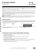
Table Of Contents

36
Multi F Ceiling Cassette Indoor Unit
Due to our policy of continuous product innovation, some specifications may change without notification.
©LG Electronics U.S.A., Inc., Englewood Cliffs, NJ. All rights reserved. “LG” is a registered trademark of LG Corp.
MA
X
MUL
TI
F
MUL
TI
F
Refrigerant Safety
ASHRAE Standards 15-2010 and 34-2010 offer guidelines that address refrigerant safety and the maximum allowable concentration of
refrigerant in an occupied space. Refrigerant will dissipate into the atmosphere, but a certain volume of air is required for this to occur safely.
For R410A refrigerant, the maximum allowable concentration of refrigerant is twenty-six (26) lbs. per 1,000 cubic feet of an occupied space.
Buildings with twenty-four (24) hour occupancy allow half of that concentration.
1
ASHRAE Standards 15 and 34 assume that if a system develops a leak, its entire refrigerant charge will dump into the area where the leak oc-
curs. To meet ASHRAE Standards 15 and 34, calculate the refrigerant concentration that may occur in the smallest room volume on the system,
and compare the results to the maximum allowable concentration number.
1
Also consult state and local codes in regards to refrigerant safety.
WARNING
Verify the maximum refrigerant concentration level in the space where the indoor unit will be installed meets the concentration limit for the application.
1
Information about ASHRAE Standard 15-2010/34-2010 and addenda current as of the date of this publication.
Figure 47: Using Nitrogen Gas During Brazing.
Auxiliary
Valve
Tape
(no air bubbles)
Do not block outlet side.
When pressure inside pipe
is above atmospheric pressure,
pinhole leaks can occur
Refrigerant Pipe
Welding Point
Regulator
Nitrogen gas
3.0 psi or less
Nitrogen
Gas
Tank
Brazing
Note:
It is imperative to keep the piping system free of contaminants and debris such
as copper burrs, slag, or carbon dust during installation.
1. All joints are brazed in the field. Multi F refrigeration system components
contain very small capillary tubes, small orifices, electronic expansion
valves, oil separators, and heat exchangers that can easily become
blocked. Proper system operation depends on the installer using best
practices and utmost care while assembling the piping system.
• Store pipe stock in a dry place and keep stored pipe capped and clean.
• Purge all pipe sections clean with dry nitrogen prior to assembly.
2. Proper system operation depends on the installer using best practices and the utmost care while assembling the piping system.
• Use adapters to assemble different sizes of pipe.
• Always use a non-oxidizing material for brazing. Do not use ux, soft solder, or anti-oxidant agents. If the proper material is not used,
oxidized lm may accumulate and clog or damage the compressors. Flux can harm the copper piping or refrigerant oil.
• Use a tubing cutter. Do not use a saw to cut pipe. De-bur and clean all cuts before assembly.
3. Brazing joints:
• Use a dry nitrogen purge operating at a minimum pressure of three (3) psig and maintain a steady ow.
• Use a 15% silver phosphorous copper brazing alloy to avoid overheating and produce good ow.
• Protect isolation valves (if present), electronic expansion valves, and other heat-sensitive control components from excessive heat with a
wet rag or heat barrier spray.
IDU to ODU / Piping Insulation
PIPING CONNECTIONS
Refrigerant Piping System Insulation
All refrigerant piping including Y-branch connections, field-provided isolation ball valves, service valves, and elbows must be properly and
completely insulated using closed cell pipe insulation (up to the indoor unit piping connections). To prevent heat loss/heat gain through the
refrigerant piping, all refrigerant piping including liquid lines and vapor lines must be insulated separately. Insulation must be a minimum 1/2″
thick, and thickness may need to be increased based on ambient conditions and local codes. Table 33 lists minimum wall thickness require-
ments for Ethylene Propylene Diene Methylene (EPDM) insulation.
Inside the outdoor unit, maximum pipe temperature is 248°F and minimum pipe temperature is -40°F. For field insulation of refrigerant piping
between outdoor units and indoor units, consider the following pipe temperature ranges for an operating heat pump system:
• Heating mode refrigerant temperature ranges: Liquid 75-118°F; High Pressure Vapor 95-220°F
• Cooling mode refrigerant temperature ranges: Liquid 75-118°F; Low Pressure Vapor 40-90°F