
Multi F Ceiling Cassette Installation Manual


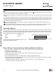
Table Of Contents

37
Installation Manual
Due to our policy of continuous product innovation, some specifications may change without notification.
©LG Electronics U.S.A., Inc., Englewood Cliffs, NJ. All rights reserved. “LG” is a registered trademark of LG Corp.
MA
X
MUL
TI
F
MUL
TI
F
Note:
Follow locals codes when selecting EPDM insulation wall thickness. Thickness in Table 33 is based on heat conductivity of 0.61 Btu/in/h/ft2/°F.
Table 33: Insulation Guidelines for Typical and Special Circumstances.
Classication
Air-conditioned location Non-air conditioned location
1. Typical location 2. Special location 3. Typical location 4. Special location
Liquid pipe
ø1/4 inches
1/2 inches 1/2 inches 1/2 inches 1/2 inches
ø3/8 inches
≥ø1/2 inches 1/2 inches 1/2 inches 1/2 inches 1/2 inches
Vapor pipe
ø3/8 inches
1/2 inches 3/4 inches 3/4 inches 1 inch
ø1/2 inches
ø5/8 inches
ø3/4 inches
1. Air-conditioned, Typical location
• When piping passes through an indoor area where the indoor unit operates, such as an apartment, classroom, ofce, mall, hospital, etc.
2. Air-conditioned, Special location
• When the location is air conditioned, but has severe temp/humidity difference due to high ceilings, such as a church, auditorium, theater, etc.
• When the location is air conditioned, but internal temperature/humidity are high, such as a bathroom, swimming pool, locker room, etc.
3. Non-air conditioned, Typical location
• When piping passes through an indoor area where the indoor unit does not operate, such as a hallway, dormitory, or school, etc.
4. Non-air conditioned, Special location (when both conditions listed below are present)
• When piping passes through an indoor area where the indoor unit does not operate.
• When the humidity is high and there is no air ow in the location where the piping is installed.
Piping Insulation
PIPING CONNECTIONS
WARNING
Ensure all refrigerant piping is insulated. Any exposed piping will cause burns if touched.
Note:
Any exposed piping may generate condensate that may damage walls, etc.; sufciently insulate all cold surfaces to prevent moisture from forming.
Figure 48: Typical Refrigerant Line Flare Fitting Insulation Detail.
No Clearance
Overlap Insulation Where the
Port and the Piping Meet
Insulation for Indoor Unit Port
(Field Supplied)
Insulation for Refrigerant
Piping (Field Supplied)
Insulation Clip (Field Supplied)
Overlap the insulation at the connection of the field-installed piping
and the indoor unit. Tape together so that no gaps exist, and secure
insulation to the rear piping housing with vinyl tape.
Ensure insulation material fits snugly against the refrigeration pipe
with no air space between the pipe surface and the surrounding
insulation.
Protect insulation inside hangers and supports with a second insula-
tion layer. Ensure insulation on all pipe passing through pipe hang-
ers, inside conduit, and/or sleeves is not compressed.
Glue all insulation joints with no air gaps. Be sure insulation materi-
al fits snugly against the refrigeration pipe with no air space between
it and the pipe. All pipe insulation exposed to the sun and outdoor
elements must be properly protected with PVC, aluminum vapor bar-
rier, or alternatively placed in a weather-resistant enclosure such as
a pipe rack with a top cover; and must meet local codes. Pay special
attention to insulating the pipes installed in a ceiling plenum.