
Multi F Engineering Manual


Wiring Diagram
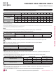
TWO-WAY VAHU INDOOR UNITS
)LJXUH0XOWL)9HUWLFDO+RUL]RQWDO$LU+DQGOLQJ,QGRRU8QLW:LULQJ'LDJUDP
: Factory Wiring
: Field Wiring
: OPTION
Connection Name Location Function
&132:(5 AC power supply AC Power line input for indoor controller
CN-MOTOR1 Fan motor output Motor output of BLDC
CN-MOTOR2 Fan motor output Motor output of BLDC
CN-FLOAT Float switch input Float switch sensing (water level sensor)
CN-PIPE/IN Suction pipe sensor Pipe in thermistor
CN-PIPE/OUT Discharge pipe sensor Pipe out thermistor
CN-ROOM Room sensor Room thermistor
CN-REMO Remote controller Remote control line
CN-OPTION Option PCB Communication between main and option
&1=21( =RQHFRQWUROOHU =RQHFRQWUROOLQH
CN-DISPLAY RF Remote controller RF Remote control line
CN-CC Dry contact Dry contact line
7DEOH:LULQJ'LDJUDP&RQQHFWLRQV
'XHWRRXUSROLF\RIFRQWLQXRXVSURGXFWLQQRYDWLRQVRPHVSHFL¿FDWLRQVPD\FKDQJHZLWKRXWQRWL¿FDWLRQ
©/*(OHFWURQLFV86$,QF(QJOHZRRG&OLIIV1-$OOULJKWVUHVHUYHG³/*´LVDUHJLVWHUHGWUDGHPDUNRI/*&RUS
146 | VERTICA L-HORIZONTAL
Multi F and Multi F MAX Indoor Unit Engineering Manual
MULTI
F
MAX
MULTI
F