
Multi F Engineering Manual


Assigning the Thermistor for Temperature Detection
Each indoor unit includes a return air thermistor assigned to sense the temperature. If a wired controller is installed, there is a choice of
sensing temperature with either the indoor unit return air thermistor or the thermistor in the wired controller. It is also an option to set both
thermistors to sense temperature so that indoor unit bases its operation on the first thermistor to reach the designated temperature differen-
tial. For applicable indoor units, an optional Remote Temperature Sensor can be used in lieu of the return air thermistor—either alone or in
conjunction with a wired controller thermistor as previously described.
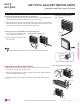
Finalizing Indoor Unit Installation
1. Verify that the side covers are closed or opened, depending on
installation requirements. Place the power wiring / communica-
tions cable in the bottom groove along the left side of the frame.
2. Reconnect the
panel connector found at the top of the indoor unit.
3. Attach the top part of the front panel, then position its tabs in the
grooves on the bottom part of the indoor unit frame.
4. To ensure the front panel tabs are securely positioned in the
grooves, adjust the panel by loosening or tightening the screws
at the bottom.
)LJXUHFinal Installation Step—Reattaching the Front Panel.
Front Panel
Connector
12
34
ART COOL GALLERY INDOOR UNITS
Installation and Best Layout Practices
'XHWRRXUSROLF\RIFRQWLQXRXVSURGXFWLQQRYDWLRQVRPHVSHFL¿FDWLRQVPD\FKDQJHZLWKRXWQRWL¿FDWLRQ
©/*(OHFWURQLFV86$,QF(QJOHZRRG&OLIIV1-$OOULJKWVUHVHUYHG³/*´LVDUHJLVWHUHGWUDGHPDUNRI/*&RUS
46 | ART COOL GALLERY™
Multi F and Multi F MAX Indoor Unit Engineering Manual
MULTI
F
MAX
MULTI
F