ENGLISH FRANÇAIS ESPAÑOL INSTALLATION MANUAL AIR CONDITIONER • Please read this installation manual completely before installing the product. • Installation work must be performed in accordance with the national wiring standards by authorized personnel only. • Please retain this installation manual for future reference after reading it thoroughly. TYPE : Multi Type http://www.lghvac.com www.lg.
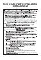
FLEX MULTI SPLIT INSTALLATION INSTRUCTIONS
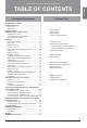
Multi Air Conditioner Installation Manual Installation Requirements Installation Parts Provided ...................................................4 Product Introduction .............................................................5 Indoor Unit.........................................................................5 Outdoor Unit ......................................................................5 Safety Precautions ................................................................
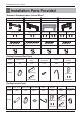
Installation Parts Provided Installation Parts Provided [Standard / Standard Libero / Artcool Mirror] Type 1 Type 2 Type 3 Type 4 Installation plate Installation plate Installation plate Installation plate Type "B" screw Type "B" screw Type "B" screw Type "C" screw Type "B" screw Type "C" screw Type "A" screw Type "A" screw Type “A” screw Type “A” screw Remote control holder Remote control holder Remote control holder Remote control holder [Ceiling Concealed Duct Type] Name Clamp metal
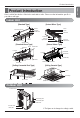
Product Introduction Here is a brief introduction of the indoor and outdoor units. Please see the information specific to your indoor unit type.
Safety Precautions Safety Precautions To prevent the injury of the user or other people and property damage, the following instructions must be followed. n Be sure to read before installing the air conditioner. n Be sure to observe the cautions specified here as they include important items related to safety. n Incorrect operation due to ignoring instruction will cause harm or damage. The seriousness is classified by the following indications.
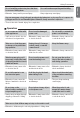
Safety Precautions • Otherwise, it may result in personal injury. Use caution when unpacking and installing. • Sharp edges may cause injury. Use a vacuum pump or Inert (nitrogen) gas when doing leakage test or air purge. Do not compress air or Oxygen and Do not use Flammable gases. Otherwise, it may cause fire or explosion. • There is the risk of death, injury, fire or explosion. n Operation Do not share the outlet with other appliances. Do not use the damaged power cord.
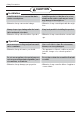
Safety Precautions CAUTION n Installation Install the drain hose to ensure that drain can be securely done. • Otherwise, it may cause water leakage. Always inspect gas leakage after the installation and repair of product. • Otherwise, it may cause the failure of product. Install the product so that the noise or hot wind from the outdoor unit may not cause any damage to the neighbors. • Otherwise, it may cause dispute with the neighbors. Keep level parallel in installing the product.
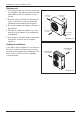
Installation of Indoor, Outdoor Unit Read completely, then follow step by step. Select the best location Indoor unit 1. Do not have any heat or steam near the unit. 2. Select a place where there are no obstacles in front of the unit. 3. Make sure that condensation drainage can be conveniently routed away. 4. Do not install near a doorway. 5. Ensure the unit is unobstructed, allow proper space on all sides according to the arrows and distance measurements in the figures. 6.
Installation of Indoor, Outdoor Unit Outdoor unit 1. If an awning is built over the unit to prevent direct sunlight or rain exposure, make sure that heat radiation from the condenser is not restricted. 2. Ensure the unit is unobstructed, allow proper space on all sides according to the arrows and distance measurements in the figures. 3. Do not place animals and plants in the path of the warm air. 4. Take the air conditioner weight into account and select a place where noise and vibration are minimum. 5.
Installation of Indoor, Outdoor Unit ENGLISH Seaside Applications and Installation 1. Air conditioners should not be installed in areas where corrosive gases, such as acid or alkaline gas, are produced. 2. Do not install the product where it could be exposed to sea wind (salty wind) directly. It can result corrosion on the product. Corrosion, particularly on the condenser and evaporator fins, could cause product malfunction or inefficient performance. 3.
Installation of Indoor, Outdoor Unit Piping length and elevation Multi Piping Type Unit : m(ft) Max Elevation Max elevation Max.Combination between each between indoor of Indoor unit indoor unit and units (h2) (Btu/h class) outdoor unit (h1) 15(49) 7.5(25) 24k 18k Max total length of all pipes (A+B)/(A+B+C)/ (A+B+C+D) 50(164) 25(82) 3(10) 24k 75(246) 25(82) 3(10) 15(49) 7.5(25) 33k 36k 75(246) 25(82) 3(10) 15(49) 7.
Installation of Indoor, Outdoor Unit Max total length Max length Outdoor Unit of all pipes of Capacity (Main + Branch Main pipe (Btu/h class) pipes) (A+B+C) 54k 145(476) 55(180) Unit : m(ft) Max length Max length of of each Branch Branch pipe pipes 90(295) Min length of each pipe (Main / Branch pipes) 15(49) 3(10) Max Elevation Max ElevaMax CombiBetween each tion nation indoor unit and Between inof indoor outdoor unit door unit (h1) (h2) 30(98) 15(49) 73k Pipe Diameter Unit : mm(inch) Indoor uni
Installation Installation [Standard / Standard Libero / Artcool Mirror Type] Connecting the piping # Standard / Artcool Mirror Type 1. Prepare the indoor unit's piping and drain hose for installation through the wall. 2. Remove the plastic tubing retainer(see the illustration on the right) and pull the tubing and drain hose away from chassis. 3. Route the indoor tubing and the drain hose to the required piping hole position. 4. Insert the piping, drain hose, and the connecting cable into the piping hole.
Installation ENGLISH # Standard Libero / Artcool Libero Type 1. Pull the screw cap at the bottom of the indoor unit 2. Remove the chassis cover from the unit by loosing screws Chassis cover Indoor unit back side view 3. Pull back the tubing holder. Pipe Port 4. Remove pipe port cover and positioning the tubing Left Right Tubing holder Backwards 5. Indoor unit installation 1) Hook the indoor unit onto the upper portion of the installation plate.
Installation Connecting the piping to the indoor unit and drain hose to drain pipe. 1. Align the center of the pipes and sufficiently tighten the flare nut by hand. Indoor unit tubing Flare nut Pipes 2. Tighten the flare nut with a wrench. Open-end wrench (fixed) Outside diameter mm inch Ø6.35 1/4 Ø9.52 3/8 Ø12.7 1/2 Ø15.88 5/8 Ø19.05 3/4 N. m 14~18 34~42 49~61 69~82 100~120 Torque kgf.m 1.4~1.8 3.5~4.3 5.0~6.2 7.0~8.4 10.0~12.2 lbf.ft 10~13 25~31 36~45 51~60 73~88 3.
Installation Plastic bands Insulation material Indoor unit pipe Connection pipe Wrap with vinyl tape Vinyl tape (wide) Pipe Vinyl tape(narrow) 3. Bundle the piping and drain hose together by wrapping them with vinyl tape over the range within which they fit into the rear piping housing section. Vinyl tape(wide) Drain hose Reroute the pipings and the drain hose across the back of the chassis. Finishing the indoor unit installation # Standard / Artcool Mirror Type 1. Remove the spacer. 2.
Installation Installation of filters 1) Detach two attached tapes from the plasma filter. Plasma Filter How To Fix The wall you select should be strong and solid enough to prevent vibration 1. Mount the installation plate on the wall with type "A" screws. If mounting the unit on a concrete wall, use anchor bolts. • Mount the installation plate horizontally by aligning the centerline using a level. 2. Measure the wall and mark the centerline.
Installation ENGLISH Wiring Connection 1. Connect the wires to the terminals on the control board individually according to the outdoor unit connection. • Ensure that the color of the wires of outdoor unit and the terminal No. are the same as those of indoor unit respectively. Terminal Block in Indoor 1(L1) 2(L2) 3 4 Connecting cable Connected to Outdoor Unit 2. Attach the Grille onto the cabinet.
Installation [Ceiling Concealed Duct Type] Ceiling dimension and hanging bolt location Installation of Unit B A Install the unit above the ceiling correctly. CASE 1 G • Apply a joint-canvas between the unit and duct to absorb unnecessary vibration. E C D POSITION OF SUSPENSION BOLT • Apply a filter Accessory at air return hole. Unit:mm(inch) Dimension C D E F G H I 9/12k 850 900 383 570 93.5 190 20.
Installation • Select and mark the position for fixing bolts. • Drill the hole for set anchor on the face of ceiling. • Insert the set anchor and washer onto the suspension bolts for locking the suspension bolts on the ceiling. • Mount the suspension bolts to the set anchor firmly. • Secure the installation plates onto the suspension bolts (adjust level roughly) using nuts, washers and spring washers.
Installation CAUTION 1. Install declination of the indoor unit is very important for the drain of the duct type air conditioner. 2. Minimum thickness of the insulation for the connecting pipe shall be 19mm(1/32 inch). Front of view • The unit must be horizontal or declined to the drain hose connected when finished installation. Ceiling Drainage hole Drain Pump use INSULATION, OTHERS THERMAL INSULATION Insulate the joint and tubes completely. All thermal insulation must comply with local requirement.
Installation 1 ENGLISH Installation of wired Remote Controller Put the installation paper on the place and determine the position and height of the fixing screws of the wired remote controller. • Refer to the printed side of the installation paper. The position of the fixing screws Plug the connecting cable into the indoor unit.
Installation Wired remote controller switch information Group Control Group control switch SWGR 1. For individual control/Master use 2. For group control/Slave use 2 1 Ceiling Height/Default E.S.P SWHI Ceiling height selection switch 1. Low ceiling 2. Standard ceiling 3. High ceiling 3 2 1 S/W 1 Select Product SWPD Product selection switch 1. Cooling Only product 2. Heat Pump product 2 1 Room Temp. Sensing 3 2 1 SWTH Indoor temperature sensor selection switch 1.
Installation ENGLISH n Necessary functions before using Trial Operation The trial operation is to check the installation status of the product. The temperature will not be controlled during trial operation. Instead the product will operate in several modes such as cooling, strong wind, comp-on. 1 If you want to set the trial operation mode, press the mode button and the Fan speed button same time for three seconds.
Installation Celsius/Fahrenheit Switching 1 If you want to change the temperature unit as the Celsius or Fahrenheit, press the Temperature control button(▼) and the Fan speed button same time for three seconds to enter the setting Mode. 2 Press the temperature control button to change the unit. Ex) Setting unit as Fahrenheit.
Installation ENGLISH Setting the Central-Control Address Please set the address while using the central controller. You don't need to set address if you don't use central controller. PQRCUCS0C Defrost Preheat Out door Room Temp 1 If you want to set the address on the display panel, press both temperature control buttons (s/t) same time for three seconds. 2 Press the temperature-increasing button to change the group number. Press the temperature-decreasing button to change the indoor unit number. e.
Installation ESP Function E.S.P function is setting the volume of each fan speed. It is for the convenience of installation. It is recommended that you should not use this function while using the remote controller. PQRCUCS0C Defrost Preheat Out door Room Temp 1 Press the mode button and the temperature increasing button(s) same time for three seconds. 2 Set the volume of each fan speed(Low, Medium, Hi) by using the temperature control button. Press the fan speed button to select the fan speed.
Installation Ceiling dimension and hanging bolt location • The dimensions of the paper model for installation are the same as those of the ceiling opening dimensions. Ceiling Ceiling board Level gauge 585~660(23 1/16~26) (Ceiling Opening) 461(18 5/32) 585~660(23 1/16~26) (Ceiling Opening) 570(22 15/32) Unit Size 517(20 3/8) Unit Size 523(20 19/32) 319(12 9/16) 570(22 15/32) 517(20 3/8) • Select and mark the position for fixing bolts and piping hole.
Installation How to Fix Keep the length of the bolt from the bracket to 40mm(1-9/16 inch) Hanging bolt (W3/8 or M10) Nut (W3/8 or M10) Flat washer for M10 (accessory) Ceiling board Spring washer (M10) ① Hanging Bolt - W 3/8 or M10 ② Nut - W 3/8 or M10 Ceiling board Keep the length of 31~34mm(1.22~1.34inch) between the air conditioner bottom surfac e and the ceiling surface Flat washer for M10 (accessory) Nut (W3/8 or M10) • The following parts are local purchasing.
Installation 1. Please fix tightly using provided screw after placing remote controller setup board on the place where you like to setup. - Please set it up not to bend because poor setup could take place if setup board bends. Please set up remote controller board fit to the reclamation box if there is a reclamation box. - Install the product so as not to make a gap with the wall side and to prevent shaking after the installation. 2. Can set up Wired remote controller cable into three directions.
Installation 3. Please fix remote controller upper part into the setup board attached to the surface of the wall, as the picture below, and then, connect with setup board by pressing lower part. - Please connect not to make a gap at the remote controller and setup boardʼs upper and lower, right and left part. - Before assembly with the installation board, arrange the Cable not to interfere with circuit parts.
Installation The decorative panel has its installation direction. Before installing the decorative panel, always remove the paper template. 1. Remove the packing and take out air inlet grille from front panel. Front grille 2. Remove the Corner covers of the panel. Coner cover 3. Fit the panel on the unit by inserting hooks as shown in picture. Hook clip Hook 4. Insert two screws on diagonal corners of panel. Do not tighten the bolts completely. (The fixing screws are included in the indoor unit box.
Installation 5. Fit the corner covers. 6. Open two screws of control panel cover. Screw 7. Connect one display connector and two vane control connectors of front panel to indoor unit PCB. The position marking on PCB is as: Display connector : CN-DISPLAY Vane control connector: CN-VANE 1,2 CN-VANE 1,2 CN-DISPLAY 8. Close the cover for control box. 9. Install the air inlet grille and Filter on the panel.
Installation Good example Bad example Air conditioner unit Air conditioner unit Air Ceiling board Cool air leakage (no good) Ceiling board Decorative panel Decorative panel Fit the insulator (this part) and be careful for cool air leakage HEAT INSULATION 1. Use the heat insulation material for the refrigerant piping which has an excellent heat-resistance [over 120°C(248°F)]. 2.
Installation [Ceiling Concealed Duct/Ceiling Cassette Type] • Drain piping must have down-slope (1/50 to 1/100): be sure not to provide up-and-down slope to prevent reversal flow. • During drain piping connection, be careful not to exert extra force on the drain port on the indoor unit. • The outside diameter of the drain connection on the indoor unit is 32mm(1 1/4 inch).
Installation ENGLISH Attention 1. Possible drain-head height is up to 700mm(27 9/16 inch). So, it must be installed below 700mm(27 9/16 inch). 1/50~1/100 MAX 700mm (27 9/16 inch) 2. Keep the drain hose downward up to 1/50~1/100 inclination. Prevent any upward flow or reverse flow in any part. 3. 5mm(3/16 inch) or thicker formed thermal insulator is provided for the drain pipe. Thermal insulator (Local supply) Drain pipe (Local supply) Unit Elbow Drain pump 4. Upward routing is not allowed. Wall 5.
Flaring Work and Connection of Piping Flaring Work and Connection of Piping Flaring work Main cause of gas leakage is defect in flaring work. Carry out correct flaring work in the following procedure. Copper tube Slanted Uneven Rough 90 1) Cut the pipes and the cable. n Use the accessory piping kit or the pipes purchased locally. n Measure the distance between the indoor and the outdoor unit. n Cut the pipes a little longer than measured distance. n Cut the cable 1.5m(4.
Flaring Work and Connection of Piping ENGLISH Connection of piping - Outdoor Align the center of the piping and sufficiently tighten the flare nut by hand. Connecting pipe order 1) A~D-UNIT gas side pipe 2) A~D-UNIT liquid side pipe (Only Indoor Units 18 kBtu/h class ) Finally, tighten the flare nut with torque wrench until the wrench clicks. • When tightening the flare nut with torque wrench ensure the direction for tightening follows the arrow on the wrench.
Flaring Work and Connection of Piping • For the units with capacity more than 48 kBtu/h, the installation piping is connectable in four directions.(refer to figure 1) • When connecting in a downward direction, knock out the knockout hole of the base pan. (refer to figure 2) Continuous → Torque wrench (250mm ) Preventing foreign objects from entering (Figure3) • Plug the pipe through-holes with putty or insulation material(procured locally)to stop up all gaps,as shown in the figure 3.
Flaring Work and Connection of Piping [unit:mm] Model Gas Pipe Liquid Pipe Ø19.05 Ø19.05 PMBL5620 Ø9.52 Ø9.52 Ø9.52 Ø19.05 Y branch A To Outdoor Unit B A B To BD Unit • Ensure that the branch pipes are attached horizontally or vertically (see the diagram below.) Horizontal plane Facing upwards Within +/- 10 A Viewed from point A in direction of arrow • Branch pipe should be insulated with the insulator in each kit.
Flaring Work and Connection of Piping Installation • This unit may be installed suspended from the ceiling or mounted on the wall. • This unit may only be installed horizontally , as shown in the diagram below.(Side B is facing up) However, it may be freely installed in any direction forward or back, and to the sides. • Be sure to leave a 600mm square opening for service and inspection as shown in the diagram below, for both ceiling - suspended installation and wall-mounted installation.
Flaring Work and Connection of Piping ENGLISH Installation of The Main Unit NOTICE : • This unit has two different installation types: (1) Ceiling-suspended type and (2) wall-mounted type. • Choose the proper installation pattern according to the location of installation. • The installation location for printed wiring board can be changed. Follow the procedure specified in the "CONNECTING THE WIRING" section to change the location.
Connecting the Cable between Indoor Unit, Distributor Unit and Outdoor Unit Connecting the Cable between Indoor Unit, Distributor Unit and Outdoor Unit Connect the cable to the Indoor unit. Connect the cable to the indoor unit by connecting the wires to the terminals on the control board individually according to the outdoor unit connection. (Ensure that the color of the wires of the outdoor unit and the terminal No. are the same as those of the indoor unit.
Connecting the Cable between Indoor Unit, Distributor Unit and Outdoor Unit • Connect refrigerant pipes and connection wires to the appropriate ports maked with matching alphabets (A, B and C) on this unit. • Follow the instructions on the wiring nameplate to connect the connection wires of indoor/outdoor units to terminal board numbers.(1, 2 and 3) Always fix each ground wire separately with a ground screw.(See the figure below.
Connecting the Cable between Indoor Unit, Distributor Unit and Outdoor Unit Connect the cable to the Outdoor unit. 1. Remove the control cover from the unit by loosening the screw. Connect the wires to the terminals on the control board individually as the following. Outdoor unit 2. Secure the cable onto the control board with the holder (clamper). Cover control Terminal block Screw 3. Re-attach the cover control to the original position using the screws.
Connecting the Cable between Indoor Unit, Distributor Unit and Outdoor Unit : WARNING: • Be sure to comply with local and national codes while running the wire from the indoor unit to the outdoor unit(size of wire and wiring method, etc). • Every wire must be connected firmly. • No wire should be allowed to touch refrigerant tubing, the compressor or any moving parts.
Connecting the Cable between Indoor Unit, Distributor Unit and Outdoor Unit Connection method of the connecting cable(Example) (1) Remove the side panel and knockouts of conduit panel. (for low voltage line) (2) Pull out connection cable through conduit. (3) After conduit to the panel, fix nut to the opposite side of panel. (4) Pass the connection cabel through the hole. (5) Properly connect the cable on the terminal block.
Checking the Drainage, Insulating the Pipe and Special Piping Applications Checking the drainage 1. Remove the Air Filter. 2. Check the drainage. • Spray one or two glasses of water upon the evaporator. • Ensure that water flows drain hose of indoor unit without any leakage. h The figure can be changed according to model.
Long Pipe Setting Long Pipe Setting 1. Open the top cover of outdoor unit. 2. Select one of the two selectable modes as follows. 3. Set the Zone as shown in Fig. 4. Close the top cover and check whether the product works normally. WARNING: Do not open the top cover or Set the pipe length when operating the product.
Air Purging and Evacuation Air and moisture remaining in the refrigerant system have undesirable effects as indicated below. 1. Pressure in the system rises. 2. Operating current rises. 3. Cooling(or heating) efficiency drops. 4. Moisture in the refrigerant circuit may freeze and block capillary tubing. 5. Water may lead to corrosion of parts in the refrigeration system.
Air Purging and Evacuation Evacuation 1. Connect the charge hose end described in the preceding steps to the vacuum pump to evacuate the tubing and indoor unit. Confirm the "Lo" knob of the manifold valve is open. Then, run the vacuum pump. The operation time for evacuation varies with tubing length and capacity of the pump. [Each Room] The vacuum pump must be operated less than 0.8torr of the gage pressure. Indoor unit Outdoor unit 2.
Charging n If installed total piping length is more than standard total length, additional refrigerant charging is necessary. Below standard total piping length, additional refrigerant charging is not required.
Charging Distributor type Models Additional charge (oz) = (( Total Main piping Length - Main Standard Length ) x 0.55 + (A Room Branch Length – Standard Length ) x 0.22 + (B Room Branch Length – Standard Length ) x 0.22 + (C Room Branch Length – Standard Length ) x 0.22 +.. ) - CF(Correction Factor) x 3.53 h CF = Max. number of connectable indoor unit – Total number of connected indoor unit • Total main pipe(A+B+C)=98ft • Each branch pipe a=33ft b=26ft c=16.
Combination indoor units ENGLISH Combination indoor units The indoor units connectable to the outdoor unit are shown below Type Standard Type Chassis Name SE Indoor Unit Capacity (Btu/h class) 12k Model Name AMNW09GDEL1 AMNW12GDEL1 [LMN095HV(T)] [LMN125HV(T)] 9k Standard Libero Type AMNW09GDBL0 [LMN096HVT] AMNW09GEBA0 [LMEN096HVT] AMNW12GDBL0 [LMN126HVT] AMNW12GEBA0 [LMEN126HVT] Artcool Libero Type Ceiling Concealed Duct Type Ceiling Cassette Type NOTICE SE AMNW09GDER1 [LMAN095HV(T)] AMNW09GDBR
Multi Air Conditioner
US 1. Please call the installing contractor of your product, as warranty service will be provided by them. 2. If you have service issues that have not been addressed by the contractor, please call 1-888-865-3026.