
Multi F LMU540HV Installation Manual


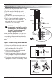


Table Of Contents

Installation Manual 45
ENGLISH
Connecting the Cable between Indoor Unit, Distributor Unit and Outdoor Unit
(1) Remove the control cover. Loosen the two
screws, and slide the cover in the direction
of the arrow.
(2) Pull out connection cable through conduit.
After conduit to the panel, fix nut to the
opposite side of panel. Pass the connection
cabel through the hole.
(3)
Perform wiring with reference the wiring diagram
on a control cover of outdoor unit. Allow 300
mm(11 13/16 inch) for the pulling-out section of
harness. Fix the wires completely with wire
clamps(4 locations).
(4) Put in the cover in the direction of the arrow
then tighten the screws.
• Connect refrigerant pipes and connection wires to the appropriate ports maked with matching
alphabets (A, B and C) on this unit.
• Follow the instructions on the wiring nameplate to connect the connection wires of indoor/outdoor
units to terminal board numbers.(1, 2 and 3) Always fix each ground wire separately with a ground
screw.(See the figure below.)
• After completing the wiring, fix the outer coating of wires securely with wire clamps. The wire
clamp on indoor unit side is furnished. Follow the procedure below to install.
• Refer to the circuit diagram on the control cover inside outdoor unit.
:
The terminal board numbers are arranged from top to bottom in order of 1, 2 and 3.
NOTICE
Warning
Do not use tapped
wires, stand wires,
extensioncords, or starbust
connections, as they may
cause overtheating,
electrical shock, or fire.
A room
B room
C room
A
B
C
CN-PWR
Connection wire for indoor units
(AWG 18-4)
Connection wire for outdoor units
(AWG 16-4)
Lock nut (field supply)
Lock nut (field supply)Lock nut (field supply)
Conduit (field supply)
Lock nut (field supply)
Lock nut (field supply)
In Case of 3 rooms
Connect the cable to the Distributor unit.