
Multi F LMU540HV Installation Manual


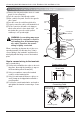


Table Of Contents

46 Multi Air Conditioner
Connecting the Cable between Indoor Unit, Distributor Unit and Outdoor Unit
Connect the cable to the Outdoor unit.
1. Remove the control cover from the unit by loos-
ening the screw.
Connect the wires to the terminals on the control
board individually as the following.
2. Secure the cable onto the control board with the
holder (clamper).
3. Re-attach the cover control to the original posi-
tion using the screws.
1(L1) 2(L2) 3 1(L1) 2(L2) 3
Indoor Unit Terminal Block
A Unit
Indoor Unit Terminal Block
B Unit
L1 L2 1(L1) 2(L2) 3(A) 3(B)
POWER SUPPLY A UNIT
B UNIT
C UNIT
D UNIT
1(L1) 2(L2) 3 1(L1) 2(L2) 3
A Unit B Unit
1(L1) 2(L2) 3(B) 3(A) 1(L1) 2(L2) 3(C) 3(D)
POWER SUPPLY A UNIT
B UNIT
Indoor Unit Terminal Block
Indoor Unit Terminal Block
A Unit
Indoor Unit Terminal Block
B Unit
Indoor Unit Terminal Block
C Unit
Indoor Unit Terminal Block
D Unit
Indoor Unit Terminal Block
E Unit
Indoor Unit Terminal Block
F Unit
Indoor Unit Terminal Block
G Unit
Indoor Unit Terminal Block
H Unit
Indoor Unit Terminal Block
1(L1) 2(L2) 3
C Unit
Indoor Unit Terminal Block
1(L1) 2(L2) 3
D Unit
Indoor Unit Terminal Block
L1 L2
36k Only
18kBtu/h class
24/36 kBtu/h class
54 kBtu/h class
BD Unit (A)
BD Unit (A)
A Room B Room C Room D Room A Room B Room C Room D Room
BD Unit (B)
BD Unit (B)
1(L1) 2(L2) 3(A) 1(L1) 2(L2) 3(B)
POWER SUPPLY
L1 L2
L(L1) N(L2) S L(L1) N(L2) S
1(L1) 2(L2) 3
L(L1) N(L2) S
1(L1) 2(L2) 3
L(L1) N(L2) S
1(L1) 2(L2) 3
L(L1) N(L2) S
1(L1) 2(L2) 3
L(L1) N(L2) S
1(L1) 2(L2) 3
L(L1) N(L2) S
1(L1) 2(L2) 3
L(L1) N(L2) S
1(L1) 2(L2) 3
L(L1) N(L2) S
1(L1) 2(L2) 3
L(L1) N(L2) S
Outdoor unit
Terminal
block
Conduit hole
Power supply
cable
Connecting cable
(to the indoor unit)
Screw
Cover control