SINGLE-ZONE ART COOLTM MIRROR WALL MOUNT ENGINEERING MANUAL Single-Zone Art Cool Mirror Systems 3/4 to 2 Tons Models: LA090HSV5 LA120HSV5 LA180HSV5 LA240HSV3
PROPRIETARY DATA NOTICE This document, as well as all reports, illustrations, data, information, and other materials are the property of LG Electronics U.S.A., Inc., and are disclosed by LG Electronics U.S.A., Inc. only in confidence. This document is for design purposes only. A summary list of safety precautions is on page 3. For more technical materials such as submittals, catalogs, installation, owner’s, and service manuals, visit www.lghvac.com. For continual product development, LG Electronics U.S.
TABLE OF CONTENTS Unit Nomenclature...........................................................................................................................................................................................................4 LG Air Conditioner Technical Solution (LATS)..........................................................................................................................................................5-6 Art Cool Mirror Product Data.........................................
UNIT NOMENCLATURE Indoor Units and Outdoor Units L A N 180 H Single Zone Art CoolTM Mirror Wall Mount Engineering Manual L = LG Frame Type: A: Art Cool™ S: Standard C: Four-Way Ceiling-Cassette D: Ceiling-Concealed Duct (Low Static) H: Ceiling-Concealed Duct (High Static) V: Vertical-Horizontal Air Handling N: Indoor Unit U: Outdoor Unit No N or U: System Nominal Capacity (Nominal cooling capacity in Btu/h): 9 = 9,000 36 = 36,000 12 = 12,000 42 = 42,000 18 = 18,000 48 = 48,000 24 = 24,000 System Ty
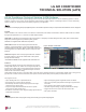
LG AIR CONDITIONER TECHNICAL SOLUTION (LATS) LG Air Conditioner Technical Solution (LATS) Software A properly designed and installed refrigerant piping system is critical to the optimal performance of LG air-conditioning systems. To assist engineers, LG offers, free of charge, LG Air Conditioner Technical Solution (LATS) software—a total design solution for LG air conditioning systems. Contact your LG Rep for the best software program for your application.
LG AIR CONDITIONER TECHNICAL SOLUTION (LATS) LATS Generates a Complete Project Report Single Zone Art CoolTM Mirror Wall Mount Engineering Manual LATS software also generates a report containing project design parameters, cooling and heating design data, system component performance, and capacity data.
ART COOL MIRROR PRODUCT DATA TM “Mechanical Specifications” on page 8 “General Data” on page 9 “Electrical Data” on page 11 “Functions, Controls, and Options”on page 12 “Dimensions” on page 13 “Acoustic Data” on page 20 “Refrigerant Flow Diagrams” on page 24 “Wiring Diagrams” on page 27 “Electrical Connections” on page 32 “Airflow and Temperature Distribution” on page 36 “Accessories” on page 41
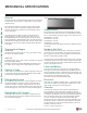
MECHANICAL SPECIFICATIONS General Figure 3: Single Zone Art Cool Mirror Wall Mount Indoor Unit. These single zone systems can operate in either cooling or heating mode. These systems are capable of changing mode within a maximum time of three (3) minutes to ensure temperature can be properly maintained.
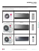
GENERAL DATA Pairing Table The following table shows the available outdoor and indoor units, along with the factory provided controller. Table 1: Single Zone Art Cool Mirror Pairing Table Indoor Unit Model Controller LAN090HSV5, LAN120HSV5 AKB74955602 LSU180HSV5 LAN180HSV5 AKB74955602 LAU240HSV3 LAN240HSV3 AKB73835320 Due to our policy of continuous product innovation, some specifications may change without notification. ©LG Electronics U.S.A., Inc., Englewood Cliffs, NJ. All rights reserved.
GENERAL DATA / SPECIFICATIONS Single Zone Art CoolTM Mirror Wall Mount Engineering Manual Table 2: Single Zone Art Cool Mirror System Specifications.
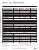
ELECTRICAL DATA Electrical Data Table 3: Single Zone Art Cool Mirror Wall Mount Electrical Data. Indoor Unit Outdoor Unit Hertz Voltage LAN090HSV5 LAN120HSV5 LAN180HSV5 LSU090HSV5 LSU120HSV5 LSU180HSV5 LAN240HSV3 LAU240HSV3 60 Voltage Range (Min. to Max.) 208 - 230 187 - 253 Voltage tolerance is ±10%. Maximum allowable voltage unbalance is 2%. MCA = Minimum Circuit Ampacity. Maximum Overcurrent Protection (MOP) is calculated as follows: (Largest motor FLA x 2.
FUNCTIONS, CONTROLS, AND OPTIONS Indoor Unit Airflow Air Purifying Functions Building Remote Central Network Integration Solution Controllers Controllers Unit Other Single Zone Art CoolTM Mirror Wall Mount Engineering Manual Table 4: Indoor Unit—Functions, Controls and Options.
INDOOR UNIT DIMENSIONS LAN090HSV5, LAN120HSV5 Dimensions for LAN090HSV5, LAN120HSV5 Figure 4: LAN090HSV5 LAN120HSV5 Unit Dimensions. Refrigerant, Drain Pipe, and Cable Knock Out Hole 2 (51) Display & Remote Controller Signal Receiver Signal Bottom 2-3/8 (60) 3-5/8 (92) Left & Right 55° Rear Right 12-1/8 (308) 2 (51) 7-9/16 (192) Air Intake Air Outlet Refrigerant, Drain Pipe and Cable Knock Out Hole 5/16 (8) Terminal Block for Power Supply and Communication Approx.
Display & Remote Controller Signal Receiver Signal Left & Right 2-1/4 (57) 3-17/32 (90) 2-7/32 (56) 50° Rear Right Bottom Air Outlet 8-11/32 (212) Air Intake Refrigerant, Drain Pipe and Cable Knock Out Hole Drain Hose Connection Approx. 9-7/16 (240) to gas pipe Approx.
INDOOR UNIT DIMENSIONS LAN240HSV3 Dimensions for LAN240HSV3 Figure 6: LAN240HSV3 Unit Dimensions. 40-9/16 3 12-3/4 9-11/16 2-1/16 2-1/16 Product Data 1-13/16 1-3/4 2-9/16 2 1 Place a level on raised tab Unit Outline 18-1/8 Return Air Grille 22-7/16 4 Ø2-9/16 Left rear piping Measuring Tape 2-1/8 4-1/8 2-11/16 Measuring Tape Hanger Right rear piping Ø2-9/16 8-1/8 Due to our policy of continuous product innovation, some specifications may change without notification. ©LG Electronics U.
OUTDOOR UNIT DIMENSIONS LSU090HSV5, LSU120HSV5 Dimensions for LSU090HSV5, LSU120HSV5 Unit : Inch (mm) 10-1/2(267) 4-3/16 (106) 31/32 (24) Drain Hole 8-Ø13/16 (20) 30-5/16 (770) Ø17-11/32 (440) 21-1/2 (545) 2-23/32 (69) Control Box 19/32 (15) 15/32 (11.5) Liquid Pipe Connection (Flared) Vapor Pipe Connection (Flared) 11-5/16 (288) 4-15/16 (125) 25° 2-3/32 (54) 25° Communication / Connection (Power) Cable Hole | PRODUCT DATA 1-7/32 (30.
OUTDOOR UNIT DIMENSIONS LSU180HSV5 Dimensions for LSU180HSV5 Figure 8: LSU180HSV5 Outdoor Unit Dimensions. Unit : Inch (mm) 6-15/32 (164) 29/32 (22.5) 15-3/32 (383) 13-3/32 (333) Control Box 13-13/32 (340) 14-3/16 (360) 1-25/32 (45) 12-19/32 (320) 17/32 (13) 5-7/8 (149) 6-25/32 (172) 6-29/32 (175) 25° 20-27/32 (529) 2-3/4 (69.5) 14° Service Valve Cover Communication / Connection (Power) Cable Hole 7-11/16 (195) 3-5/32 (79.
OUTDOOR UNIT DIMENSIONS LAU240HSV3 Dimensions for LAU240HSV3 Figure 9: LAU240HSV3 Unit Dimensions. 34-1/4 14-3/16 12-19/32 6-5/16 Item No. 1 2 3 4 5 6 Part Name Discharge air grille 12-5/8 5-7/8 2-3/16 13-1/8 Ø 20-7/8 21-1/8 18 | PRODUCT DATA 3-1/8 2 15-7/16 13-3/4 31-1/2 30-7/8 Single Zone Art CoolTM Mirror Wall Mount Engineering Manual 21-1/2 Center of gravity [Unit : inch] Due to our policy of continuous product innovation, some specifications may change without notification.
OUTDOOR UNIT CORNER WEIGHT AND CENTER OF GRAVITY DIMENSIONS Figure 10: LSU090-120-180HSV5 Outdoor Unit Corner Weight and Center of Gravity Dimensions. d A D e c C B b Product Data a Table 5: LSU090-120-180HSV5 Outdoor Unit Corner Weight and Center of Gravity Dimensions. Model No. Weight (lb.) Center of Gravity (in.) Leg (in.) Corner Weight (lb.) Shipping Net a b c d e A B C D LSU090HSV5, LSU120HSV5 78.9 74.1 19-31/32 9-11/32 5-21/32 22 12-31/32 9.5 11.0 26.8 26.
ACOUSTIC DATA Indoor Units Indoor Unit Sound Pressure Measurement Figure 11: Art Cool Mirror Indoor Unit Sound Level Measurement. • Measurements are taken 3.3 ft away from the front of the unit. • Sound pressure levels are measured in dB(A) with a tolerance of ±3. • Data is valid at nominal operation conditions. Operating conditions are assumed to be standard.
INDOOR ACOUSTIC DATA Indoor Units LAN180HSV5 Cooling and Heating Sound Pressure Diagrams Figure 14: LAN180HSV5 Cooling Sound Pressure Level Diagram. Figure 15: LAN180HSV5 Heating Sound Pressure Level Diagram. Product Data LAN240HSV3 Sound Pressure Diagrams Figure 16: Sound Pressure Levels for LAN240HSV3 Indoor Units.
ACOUSTIC DATA Outdoor Units Outdoor Unit Sound Pressure Level Measurement Figure 17: Outdoor Unit Sound Level Measurement. Single Zone Art CoolTM Mirror Wall Mount Engineering Manual Center of Outdoor Unit 3.28 ft Outdoor Unit Sound Pressure Levels • Measurements are taken 3.3 ft away from the front of the unit. • Sound pressure levels are measured in dB(A) with a tolerance of ±3. • Data is valid at nominal operation conditions. Operating conditions are assumed to be standard.
ACOUSTIC DATA Outdoor Units LSU180HSV5 Cooling and Heating Sound Pressure Diagrams Figure 20: LSU180HSV5 Cooling Sound Pressure Level Diagram. Figure 21: LSU180HSV5 Heating Sound Pressure Level Diagram. Product Data LAU240HSV3 Sound Pressure Diagrams Figure 22: LAU240HSV3 Sound Pressure Level Diagram.
REFRIGERANT FLOW DIAGRAMS Refrigerant Flow Diagram for LAN / LSU090, 120HSV5 Figure 23: Refrigerant Flow Diagram for LA090HSV5, LA120HSV5 Units.
REFRIGERANT FLOW DIAGRAMS Refrigerant Flow Diagrams for LAN / LSU180HSV5 Figure 24: Refrigerant Flow Diagram for LA180HSV5 Units.
REFRIGERANT FLOW DIAGRAMS Refrigerant Flow Diagrams for LAN / LAU240HSV3 Figure 25: Refrigerant Flow Diagram for LA240HSV3 Units.
INDOOR UNIT WIRING DIAGRAM LAN090HSV5, LAN120HSV5, LAN180HSV5 Wiring Diagram for LAN090HSV5, LAN120HSV5, LAN180HSV5 Figure 26: Wiring Diagram for LAN090HSV5, LAN120HSV5, LAN180HSV5 Units. Product Data Due to our policy of continuous product innovation, some specifications may change without notification. ©LG Electronics U.S.A., Inc., Englewood Cliffs, NJ. All rights reserved. “LG” is a registered trademark of LG Corp.
INDOOR UNIT WIRING DIAGRAM LAN240HSV3 Wiring Diagram for LAN240HSV3 Single Zone Art CoolTM Mirror Wall Mount Engineering Manual Figure 27: Wiring Diagram for LAN240HSV3 Units. Auxiliary heater relay kit is not available on single-zone wall-mounted indoor units connected to a single-zone outdoor unit. 28 | PRODUCT DATA Due to our policy of continuous product innovation, some specifications may change without notification. ©LG Electronics U.S.A., Inc., Englewood Cliffs, NJ. All rights reserved.
OUTDOOR UNIT WIRING DIAGRAM LSU090HSV5, LSU120HSV5 Wiring Diagram for LSU090,120HSV5 Figure 28: Wiring Diagram for LSU090HSV5, LSU120HSV5 Units. Product Data Due to our policy of continuous product innovation, some specifications may change without notification. ©LG Electronics U.S.A., Inc., Englewood Cliffs, NJ. All rights reserved. “LG” is a registered trademark of LG Corp.
OUTDOOR UNIT WIRING DIAGRAM LSU180HSV5 Wiring Diagram for LSU180HSV5 Single Zone Art CoolTM Mirror Wall Mount Engineering Manual Figure 29: Wiring Diagram for LSU180HSV5 Units. 30 | PRODUCT DATA Due to our policy of continuous product innovation, some specifications may change without notification. ©LG Electronics U.S.A., Inc., Englewood Cliffs, NJ. All rights reserved. “LG” is a registered trademark of LG Corp.
OUTDOOR UNIT WIRING DIAGRAM LAU240HSV3 Wiring Diagram for LAU240HSV3 Figure 30: Wiring Diagram for LAU240HSV3 Units. Product Data Due to our policy of continuous product innovation, some specifications may change without notification. ©LG Electronics U.S.A., Inc., Englewood Cliffs, NJ. All rights reserved. “LG” is a registered trademark of LG Corp.
ELECTRICAL CONNECTIONS Single Zone Art CoolTM Mirror Wall Mount Engineering Manual General Power Wiring / Communications Cable Guidelines • • • • • • • • Follow manufacturer’s circuit diagrams displayed on the inside of the control box cover. Have a separate power supply for the indoor units. Provide a circuit breaker switch between the power source and the indoor unit. Confirm power source specifications. Properly ground the outdoor unit and the indoor unit per NEC and local codes.
ELECTRICAL CONNECTIONS Figure 31: LA90HSV5 and LA120HSV5 General Power / Communications System Schematic. Power Supply Figure 32: LA180HSV5 General Power / Communications System Schematic. Power Supply Circuit Breaker Circuit Breaker Indoor Unit Ground Wiring Indoor Unit Ground Wiring Outdoor Unit Outdoor Unit Figure 33: LA090-120HSV5 System Electrical Connections. Figure 34: LA180HSV5 System Electrical Connections. 208/230 VAC Figure 35: LA240HSV3 System Electrical Connections.
ELECTRICAL CONNECTIONS Controller Options Single Zone Art Cool Mirror Wall Mount systems include a wireless handheld remote controller (Model No. AKB74955602), but optional LG-suppled wired controllers are available. See “Functions, Controls, Options”, or contact an LG representative for more information. Figure 36: AKB74955602 Wireless Handheld Remote Controller. Buttons may differ depending on model type. • Display Panel: Displays operation conditions.
ELECTRICAL CONNECTIONS Wired Controller Placement Wired controllers include a sensor to detect room temperature. To maintain comfort levels in the conditioned space, the wired controller must be installed in a location away from direct sunlight, high humidity, and where it could be directly exposed to cold air.
AIRFLOW AND TEMPERATURE DISTRIBUTION Single Zone Art CoolTM Mirror Wall Mount Engineering Manual Table 11: Art Cool Mirror Wall Mount Outdoor Unit Air Flow Rate and Static Pressure. Model No. Air Flow Rate (CFM) Static Pressure (in. WG) LSU090HSV5, LSU120HSV5 1,165 0.0329 LSU180HSV5, LA240HSV3 2,119 0.0384 LAN090HSV5 and LAN120HSV5 Cooling Air Velocity m/s (ft./s) Temperature °C (°F) 2(6.6) 0.3(1) 1(3.3) 0.5(1.6) m 10 8 6 4 2 0 ft. 32.8 26.2 19.7 13.1 6.6 0 m 2 ft. 6.6 1 3.
AIRFLOW AND TEMPERATURE DISTRIBUTION LAN090HSV5 and LAN120HSV5, continued. Heating Air Velocity m/s (ft./s) 0.3(1) 0.5(1.6) Temperature °C (°F) 1(3.3) 1.5(4.9) 2(6.6) m 10 8 6 4 2 0 ft. 32.8 26.2 19.7 13.1 6.6 0 m 2 ft. 6.6 1 3.3 0 0 32(90) 24(75) 26(79) 28(82) 30(86) m 10 8 6 4 2 0 ft. 32.8 26.2 19.7 13.1 6.6 0 m 2 ft. 6.6 1 3.3 0 0 Side View Discharge Angle : 55˚ (From the floor Vertical Louver : Center Fan Speed : Power ) Air Velocity m/s (ft.
AIRFLOW AND TEMPERATURE DISTRIBUTION LAN180HSV5 Cooling Single Zone Art CoolTM Mirror Wall Mount Engineering Manual Air Velocity m/s (ft./s) Temperature °C (°F) 2(6.6) 0.3(1) 0.5(1.6) 1(3.3) 1.5(4.9) m 10 8 6 4 2 0 ft. 32.8 26.2 19.7 13.1 6.6 0 m 2 ft. 6.6 1 3.3 0 0 28(82) 22(72) 24(75) 26(79) 18(64) 2 m ft. 6.6 1 3.3 0 0 m 10 8 6 4 2 0 ft. 32.8 26.2 19.7 13.1 6.
AIR FLOW AND TEMPERATURE DISTRIBUTION LAN180HSV5, continued. Heating Air Velocity m/s (ft./s) 0.3(1) 0.5(1.6) Temperature °C (°F) 1(3.3) 1.5(4.9) 2(6.6) m 10 8 6 4 2 0 ft. 32.8 26.2 19.7 13.1 6.6 0 m 2 ft. 6.6 1 3.3 0 0 m 24(75) ft. 6.6 32(90) 2 30(86) 28(82) 26(79) m 10 8 6 4 2 0 ft. 32.8 26.2 19.7 13.1 6.6 0 1 3.3 0 0 Side View Discharge Angle : 45˚ (From the floor Vertical Louver : Center Fan Speed : Power ) Air Velocity m/s (ft./s) m ft. 5 16.
AIRFLOW AND TEMPERATURE DISTRIBUTION LAN240HSV3 Cooling and Heating Cooling Heating Discharge angle:45° Discharge angle:50° Single Zone Art CoolTM Mirror Wall Mount Engineering Manual Air velocity [ft/s] Air velocity [ft/s] 4.9 1.6 26.2ft 23ft 19.7ft 16.4ft 13.1ft 9.8ft 3.3 2.5 6.6ft 8.9ft 6.6ft 6.6ft 4.9 4.0ft 4.1 3.3ft 8.9ft 0ft 0ft Te mperature [˚F] 8.9ft 1.6 26.2ft 23ft 19.7ft 16.4ft 13.1ft 3.3 2.5 9.8ft 6.6ft 4.0ft 4.1 3.3ft 0ft Te mperature [˚F] 8.9ft 6.6ft 26.
ACCESSORIES LG Monitoring View (LGMV) Diagnostic Software and Cable Additional screens can be accessed by tabs on the main screen: 1.
ACCESSORIES Single Zone Art CoolTM Mirror Wall Mount Engineering Manual LG Smart Inverter Monitoring System (SIMS) SIMS can be used to display and graph operational data for single zone systems and respective components (indoor unit and outdoor unit). SIMS also displays error codes and a troubleshooting guide. SIMs consists of a hardware Wireless Local Area Network (WLAN) module, an interface cable, and a free downloadable application (app) for iOS® or Android™.
ART COOL MIRROR TM PERFORMANCE DATA “Cooling Capacity Data” on page 44 “Heating Capacity Data” on page 46 “Maximum Heating Capacity Data” on page 48 “Equipment Selection Procedure” on page 50
PERFORMANCE DATA Cooling Capacity LA090HSV5, LA120HSV5 Cooling Capacity Table for LA090HSV5 (LAU090HSV5 + LAN090HSV5) Table 12: LAU090HSV5 / LAN090HSV5 Cooling Capacities. Single Zone Art CoolTM Mirror Wall Mount Engineering Manual Outdoor Air Temp. (°F DB) 0 5 7 10 14 23 25 30 35 40 45 50 55 60 65 70 75 80 85 90 95 100 105 110 115 118 122 64 / 53 TC SHC 5.45 5.34 5.38 5.44 5.51 5.92 6.01 6.24 6.47 6.70 6.94 7.17 7.40 7.63 7.56 7.49 7.42 7.36 7.29 7.22 7.15 6.96 6.77 6.59 6.35 6.21 6.02 4.52 4.46 4.
PERFORMANCE DATA Cooling Capacity LA180HSV5, LA240HSV3 Cooling Capacity Table for LA180HSV5 (LAU180HSV5 + LAN180HSV5) Table 14: LAU180HSV5 / LAN180HSV5 Cooling Capacities. Outdoor Air Temp. (°F DB) 10.90 10.69 10.76 10.87 11.02 11.83 12.02 12.48 12.95 13.41 13.87 14.34 14.80 15.27 15.13 14.99 14.85 14.71 14.57 14.43 14.29 13.92 13.55 13.17 12.70 12.42 12.05 8.68 8.56 8.64 8.76 8.91 9.57 9.72 10.10 10.47 10.85 11.23 11.60 11.98 12.35 12.24 12.13 12.02 11.91 11.79 11.68 11.57 11.27 10.96 10.66 10.28 10.
PERFORMANCE DATA Heating Capacity LA090HSV5, LA120HSV5 Heating Capacity Table for LA090HSV5 (LAU090HSV5 + LAN090HSV5) Table 16: LAU090HSV5 / LAN 090HSV5 Heating Capacities. Indoor Air Temperature (°F DB / °F WB) Outdoor Air Temp. Single Zone Art CoolTM Mirror Wall Mount Engineering Manual °FDB -3 0 1 6 10 16 17 19 24 32 41 43 47 53 59 64 70 75 °FWB -4 -1 0 5 9 14 15 17 23 30 38 40 43 50 53 57 61 65 TC 60 5.56 6.05 6.13 6.40 6.69 6.90 6.94 7.04 7.72 9.25 10.62 10.96 11.47 11.58 11.85 12.10 12.33 12.
PERFORMANCE DATA Heating Capacity LA180HSV5, LA240HSV3 Heating Capacity Table for LA180HSV5 (LAU180HSV5 + LAN180HSV5) Table 18: LAU180HSV5 / LAN180HSV5 Heating Capacities. Outdoor Air Temp. °FDB °FWB -3 0 1 6 10 16 17 19 24 32 41 43 47 53 59 64 70 75 -4 -1 0 5 9 14 15 17 23 30 38 40 43 50 53 57 61 65 TC 60 11.02 11.99 12.15 12.69 13.25 13.67 13.76 13.95 15.30 18.34 21.04 21.72 22.73 22.96 23.48 23.98 24.43 24.77 PI 1.15 1.27 1.28 1.32 1.37 1.38 1.40 1.42 1.48 1.59 1.70 1.73 1.76 1.78 1.80 1.84 1.
PERFORMANCE DATA Maximum Heating Capacity LA090HSV5, LA120HSV5 Maximum Heating Capacity Table for LA090HSV5 (LAU090HSV5 + LAN090HSV5) Table 20: LA090HSV5 Maximum Heating Capacities. Single Zone Art CoolTM Mirror Wall Mount Engineering Manual Outdoor Air Temp. °FDB °FWB -3 0 1 6 10 16 17 19 24 32 41 43 47 53 59 64 70 75 TC -4 -1 0 5 9 14 15 17 23 30 38 40 43 50 53 57 61 65 60 8.43 8.90 9.10 10.10 10.63 11.12 11.25 11.39 12.48 14.23 16.20 16.64 17.53 17.98 18.21 18.35 18.42 18.37 PI TC 0.92 0.93 0.
PERFORMANCE DATA Maximum Heating Capacity LA180HSV5, LA240HSV3 Maximum Heating Capacity Table for LA180HSV5 (LAU180HSV5 + LAN180HSV5) Table 22: LA180HSV5 Maximum Heating Capacities. Outdoor Air Temp. °FDB °FWB -3 0 1 6 10 16 17 19 24 32 41 43 47 53 59 64 70 75 -4 -1 0 5 9 14 15 17 23 30 38 40 43 50 53 57 61 65 TC 60 16.99 17.95 18.35 20.37 21.44 22.43 22.68 22.96 25.99 30.84 36.30 37.52 39.96 41.00 41.52 41.85 41.99 41.89 PI 2.30 2.32 2.33 2.40 2.43 2.45 2.44 2.47 2.72 3.08 3.36 3.45 3.68 3.75 3.
EQUIPMENT SELECTION PROCEDURE Correction Factors Cooling / Heating Correction Factors Single Zone Art CoolTM Mirror Wall Mount Engineering Manual For Single Zone Art Cool Mirror Wall Mounted systems, calculate the equivalent length of the liquid line from the outdoor unit to the indoor unit. Also, determine the elevation difference of the indoor unit above or below the outdoor unit. Find corresponding cooling or heating capacity correction factors as shown below.
EQUIPMENT SELECTION PROCEDURE Correction Factors Defrost Correction Factor for Heating Operation The outdoor unit heating capacity may need to be adjusted for frost accumulation on air-cooled systems. If design day conditions are below the dewpoint of the surrounding air, frost may not be a problem and no correction factor is needed. In certain weather conditions, however, frost may form and accumulate on the air-cooled outdoor unit coil and impact the coils ability to transfer heat.
ART COOL MIRROR TM APPLICATION GUIDELINES “Placement Considerations” on page 53 “Installing Outdoor Units Indoors” on page 58 “Refrigerant Piping Design” on page 61
PLACEMENT CONSIDERATIONS Indoor Unit Selecting the Best Location for the Indoor Unit Follow recommended best practices when choosing an indoor location for the single zone indoor unit. Figure 43: Single Zone Art Cool Mirror Wall Mount Indoor Unit Clearance Requirements.
PLACEMENT CONSIDERATIONS Outdoor Unit Selecting the Best Location for the Outdoor Unit Single Zone Art CoolTM Mirror Engineering Manual Do not install the unit in an area where combustible gas may generate, flow, stagnate, or leak. These conditions can cause a fire, resulting in bodily injury or death. • Do not install the unit in a location where acidic solution and spray (sulfur) are often used as it can cause bodily injury or death.
PLACEMENT CONSIDERATIONS Outdoor Unit Planning for Snow and Ice, continued. When deciding on a location to place the outdoor unit, be sure to choose an area where run-off from defrost will not accumulate and freeze on sidewalks or driveways, which may create unsafe conditions. Properly install and insulate any drain hoses to prevent the hose from freezing, cracking, leaking, and causing unsafe conditions from frozen condensate.
PLACEMENT CONSIDERATIONS Outdoor Unit Oceanside Applications Use of a Windbreak to Shield from Sea Wind Figure 47: Oceanside Placement Using Windbreak. Windbreak Ocean winds may cause corrosion, particularly on the condenser and evaporator fins, which, in turn could cause product malfunction or inefficient performance. Single Zone Art CoolTM Mirror Engineering Manual • • • • • • Avoid installing the outdoor unit where it would be directly exposed to ocean winds.
PLACEMENT CONSIDERATIONS Outdoor Unit Minimum Allowable Clearance and Service Access Requirements Proper clearance for the outdoor unit coil is critical for proper operation. When installing the outdoor unit, consider service, inlet and outlet, and minimum allowable space requirements as illustrated in the diagrams below. • Include enough space for airflow and for service access.
PLACEMENT CONSIDERATIONS Installing Outdoor Units Indoors Single Zone Art CoolTM Mirror Engineering Manual Installing Outdoor Units Indoors Single Zone Art Cool Mirror Wall Mount outdoor units are engineered to be mounted outdoors and include technology designed to minimize the negative effects of winter weather’s freezing rain, sleet, and snow. Some building projects, however, necessitate placing the HVAC outdoor units indoors: • Lack of ground space.
PLACEMENT CONSIDERATIONS Installing Outdoor Units Indoors Provide a means to drain the condensate generated during heating mode and defrost cycle in addition to rainwater that infiltrates the inlet louver enclosed area. • Install a field-provided drain pan under the outdoor units and provide a path to a nearby floor drain.
PLACEMENT CONSIDERATIONS Installing Outdoor Units Indoors Open Rate by Louver Radian Figure 52: Open Rate by Louver Radian Formula. W ho H ≤ 15 ho = h * COS Total Area (A) = H * W Number of Open Spaces (N) = (Number of Louvers - 1) Effective Area (Af) = ho * W * N Louver Open Rate (n) = Af / A Af = A * n Side View Effective Cross Section Area Front View Confirming Air Flow Rate / Total Opening Rate Figure 53: Example of Installing Outdoor Unit Indoors. • Example: LSU180HSV5.
REFRIGERANT PIPING DESIGN Design Guideline Summary Device Connection Limitations Figure 54: Single Zone Art Cool Mirror Wall Mount System Layout. A single-zone system consists of one outdoor unit and one indoor unit. One of the most critical elements of a single-zone system is the refrigerant piping. If the connection piping is not within allowable limits, there will be reliability, performance, noise, and vibration issues.
20001747 ISO 9001: 2008 LG ELECTRONICS INC. LG Electronics Commercial Products Support 1-888-865-3026 USA Follow the prompts for commercial A/C products. LG Electronics, U.S.A., Inc. Air Conditioning Technologies 4300 North Point Parkway Alpharetta, Georgia 30022 www.lghvac.