
Installation Manual


55
Electrical System Installation
Due to our policy of continuous product innovation, some specifications may change without notification.
©LG Electronics U.S.A., Inc., Englewood Cliffs, NJ. All rights reserved. “LG” is a registered trademark of LG Corp.
ELECTRICAL SYSTEM INSTALLATION
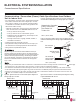
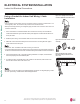
Figure 91: Example of an Indoor Unit
Knockout.
1(L1) 2(L2) 3
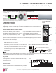
Installing the Indoor Unit Communication / Connection
(Power) Cable
The indoor units have knockout access holes for the communication / connection (power) cable,
with a choice of left or right side wiring installation. Depending on the installation and application
requirements, choose which side to knock out the access hole before applying the steps below. If
a conduit will be used to protect the cable from the indoor unit to the outdoor unit, see “Using a Con-
duit for Indoor Unit Wiring / Cable Installation” on the next page.
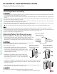
1. The terminal block is located on the bottom right side of the front of the indoor unit. Route the
power wiring / communications (connection) cable through the pre-chosen access hole.
2. The terminal block is protected by a metal control box cover. To access the terminals, unscrew
the screw holding the control box cover in place, and push the cover up.
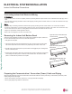
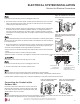
3. Unscrew the screw to the cable clamp. Open the cable clamp.
4. Using a JIS screwdriver, connect the cable terminals to the terminal block. Ensure wire color and
terminal number of the indoor unit matches those of the outdoor unit. See also indoor unit wiring
diagram found on its bottom cover, and outdoor unit wiring diagram on the inside of its chassis
cover.
5. When the wiring is complete, close the clamp cord, secure it with the screw.
Figure 92: Opening the Control Box
Cover.
Figure 93: Opening the Cable Clamp.
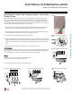
6. Close the control box cover, and secure it with the screw.
The connections in the indoor unit control box can become loose during shipping and through typical use.
Check that all of the connections are secure. If the connections are loose, the cables and terminals can
EHFRPHGDPDJHGFDXVLQJVSDUNV¿UHHOHFWULFVKRFNSK\VLFDOLQMXU\DQGRUGHDWK
• Each wire must be securely attached to the terminal block.
• Ground cable must be longer than the other wires.
Figure 94: Installing the Cable / Wiring. Figure 95: Securing the Cable Clamp. Figure 96: Closing the Control Box
Cover.
,QGRRU8QLW(OHFWULFDO&RQQHFWLRQV