
Art Cool Premier Installation Manual


53
Electrical System Installation
Due to our policy of continuous product innovation, some specifications may change without notification.
©LG Electronics U.S.A., Inc., Englewood Cliffs, NJ. All rights reserved. “LG” is a registered trademark of LG Corp.
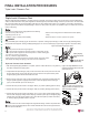
ELECTRICAL SYSTEM INSTALLATION
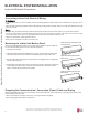
Controller Options
Handheld Remote Controller
Single Zone Art Cool Premier Wall Mounted systems include a wireless handheld remote controller (Part No.
AKB74955602). Optional LG-suppled wired controllers are available. See “Functions, Controls, Options”in the
Engineering Manual, or contact an LG representative for more information.
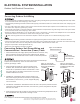
Wireless Handheld Remote Controller features:
• Display Panel: Displays operation conditions.
• On / Off Button: Turns system operation on and off.
• Mode Button: Selects the operation mode: Cooling,
Heating, Auto, Dry (Dehumidification), or Fan.
• Temp Up / Down Buttons: Adjusts the desired room
temperature in the different modes.
• Fan Speed Button: Sets desired fan speed.
• Reset: Initializes the handheld remote control set-
tings.
Dry Contact
A Dry Contact can also be connected to the Art Cool Premier indoor
unit using the CN-CC connection on the indoor unit PCB. The Dry
Contact DC is shipped with a specific connector that is used to con-
nect to the indoor unit.
Central Controller
Additionally, Single Zone Art Cool Premier systems can be con-
nected to a central controller if a PI-485 VNet Accessory is installed
in the outdoor unit. See the Central Controller manual for wiring
specifications.
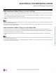
Figure 84: Schematic of a Single Zone System When the Wiring is GREATER THAN 130 Feet.
Wired Controller Connections
Optional controllers (see the Single Zone Art Cool Premier Wall-Mounted Engineering Manual, or contact an
LG representative for more information) connect to the Single Zone Art Cool Premier Piping Wall-Mounted
indoor unit in one of two different ways.
1. LG Wired Remote Extension Cable with Molex plug (PZCWRC1; sold separately) that connects to the CN-
REMO terminal on the indoor unit PCB.
2. Field-supplied controller cable that connects to the indoor unit
terminal block (must be at least UL2547 or UL1007, and at least
FT-6 rated if local electric and building codes require plenum
cable usage). Communication cable from indoor unit to remote
controller(s) is to be 22 AWG, 3-conductor, twisted, stranded,
unshielded. Wiring must comply with all applicable local and
national codes.
Figure 85: AKB74955602
Wireless Handheld Remote
Controller.
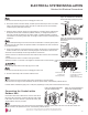
:KHQXVLQJ¿HOGVXSSOLHGFRQWUROOHUFDEOHPDNHVXUHWRFRQQHFWWKH\HOORZWR\HOORZFRPPXQLFDWLRQVZLUHUHGWRUHG9SRZHUZLUHDQGEODFN
to black (ground wire) terminals from the remote controller to the indoor unit terminal blocks.
Verify the connectors are properly inserted.
C/BOX Cable (Plug type)
Extension cable
To Indoor Unit
CN-REMO
Terminal
TEMP
FAN
SPEED
OPER
MODE
Figure 86: PZCWRC1 LG Wired Remote Extension Cable.
Figure 87: Wired Controller Connections on the Indoor Unit Terminal
Block.
Power
Supply
1(L1) (Power, L)
2(L2) (Neutral, N)
G (Ground)
Power Flow: L ĺ N
Diagram is an example of communication and power
cables when the wiring is GREATER THAN 130 feet.
Terminals may be labeled differently depending on the model.
Outdoor and Indoor Unit a
pp
earances ma
y
var
y
de
p
endin
g
on the model.
Communication Flow: Comm ĺ N
3 (Communications)
GREATER THAN 130 feet: Must Separate Communications and Ground (G) Cable from the Power
(1[L1]) and Neutral (2[L2]) Cable at Least Two (2) Inches.
At Least Two (2) Inches
Display
Button
Screen
*
*
*
Reset
Indoor Unit Terminal
BR BL
RD
GR/YL
&RQQHFWLRQVDQG6SHFL¿FDWLRQV&RQWUROOHU2SWLRQV