
Owner's Manual


Connection
diagram
9
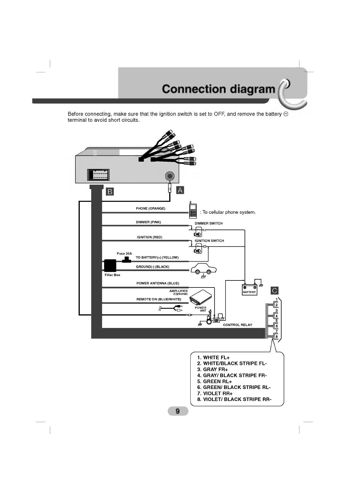
Before
connecting,
make
sure
that
the
ignition
switch
is
set
to
OFF,
and
remove
the
battery
#
terminal
to
avoid
short
circuits.
DIMMER
(PINK)
PHONE
(ORANGE)
IGNITION
(RED)
POWER
ANTENNA
(BLUE)
REMOTE
ON
(BLUE/WHITE)
TO
BATTERY(+)
(YELLOW)
GROUND(-)
(BLACK)
Filter
Box
Fuse
20A
AMPLLIFIER
(Optional)
POWER
ANT
CONTROL
RELAY
DIMMER
SWITCH
IGNITION
SWITCH
BATTERY
1.
WHITE
FL+
2.
WHITE/BLACK
STRIPE
FL-
3.
GRAY
FR+
4.
GRAY/
BLACK
STRIPE
FR-
5.
GREEN
RL+
6.
GREEN/
BLACK
STRIPE
RL-
7.
VIOLET
RR+
8.
VIOLET/
BLACK
STRIPE
RR-
A
B
C
:
To
cellular
phone
system.