
Install Instructions
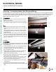
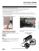
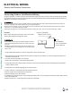


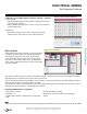
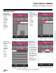
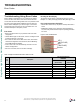
Table Of Contents

42
Single Zone High Efciency Wall Mounted Installation Manual
Due to our policy of continuous product innovation, some specifications may change without notification.
©LG Electronics U.S.A., Inc., Englewood Cliffs, NJ. All rights reserved. “LG” is a registered trademark of LG Corp.
ELECTRICAL WIRING
Indoor Unit Electrical Connections
Overview - Connecting Indoor Unit Electrical Wiring
The general guidelines for connecting electrical and communication cables to the indoor unit are the same for each Single Zone High Efficien-
cy Wall Mount system, however, the actual connections on the terminal block will differ. See each illustration for the model that you are wiring
for correct contact on each terminal block. Depending on your indoor unit, the location of the terminal block on the indoor unit might vary
slightly from the images shown in this section.
•Besurethatmainpowertotheunitiscompletelyoffbeforepro-
ceedingwiththesesteps.
•Followallsafetyandwarninginformationoutlinedatthebeginning
andthroughoutthismanual.Failuretodosomaycausebodilyinjury.
Procedure
BesurethereisnopowergoingthroughtheSingleZonesystembefore
proceedingwiththeseconnectionsastheremaybeariskofelectrical
shockandbodilyinjury.
1. At the bottom panel of the indoor unit, unsnap the latches which
cover the phillips screw heads as shown in Figure 57.
•Normally, there are three (3) screws on the panel, however, your
indoor unit model may differ.
2. Using a phillips head screwdriver, remove the screws from the
bottom panel of the indoor unit and set aside (Figure 58).
3. Remove the bottom panel (Figure 59).
•Removal is necessary to gain access to the terminal block which is
situated at the bottom of most indoor units.
•Note that the electrical/communications wiring is usually routed
through the back/bottom of the indoor unit (through a knockout
panel) as shown on the next page (Figure 60).
4. Using a screwdriver, connect the wires as shown on the next
page (Figure 61).
•Each wire should be securely attached to the terminal block.
•Pay attention to the location/connection of the green/yellow ground
cable.
Figure 57: Latch over Screws on Bottom Panel, Indoor Unit
Figure 58: Remove Screws from Bottom Panel
Figure 59: Remove (and Reattachment) Bottom Panel
•Followallsafetyandwarninginformationoutlinedatthebegin-
ningandthroughoutthismanual.Failuretodoso,maycauseunit
failure.
•SomeunitsmightrequireyoutoremovetheControlCoverfrom
theterminalblockarea.MostControlCoversareattachedwitha
phillipsscrewhead.
•Connecttheelectricalcabletotheindoorunitbyconnectingthe
wirestotheterminalsonthecontrolboardindividuallyaccordingto
theoutdoorunitconnection.Besurethatthecolorofthewiresat
theoutdoorunitalongwiththeterminalnumbersarethesameas
thosefortheindoorunit.