
Install Instructions
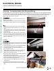
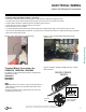
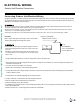


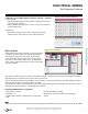
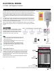
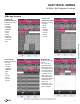
Table Of Contents

44
Single Zone High Efciency Wall Mounted Installation Manual
Due to our policy of continuous product innovation, some specifications may change without notification.
©LG Electronics U.S.A., Inc., Englewood Cliffs, NJ. All rights reserved. “LG” is a registered trademark of LG Corp.
ELECTRICAL WIRING
Outdoor Unit Electrical Connections
Connecting Outdoor Unit Electrical Wiring
The general guidelines for connecting electrical and communication cables to the outdoor unit are the same for each Single Zone High Effi-
ciency Wall Mount system, however, the actual connections on the terminal block will differ. See each illustration for the model that you are
installing for correct wiring of each terminal block.
•Besurethatmainpowertotheunitiscompletelyoffbeforeproceedingwiththesesteps.Followallsafetyandwarninginformationout-
linedatthebeginningofthismanual.Failuretodoso,maycausebodilyinjury.
•Besurethatacircuitbreakerorsomeotheremergencypowercutoffdeviceisinplacebeforeanypowerwiringisdonetothesystem.
Failuretodoso,maycausebodilyinjuryordeath.
•Nevertouchanypowerlinesorlivecablesbeforeallpoweriscutofftothesystem.Todoso,maycausebodilyinjuryordeath.
Air
Conditioner
Main Power Source
Circuit Breaker
Use a circuit breaker
or time delay fuse
Figure 63: Circuit Breaker
Procedure
Refer to Figure 63 at right for an example of how a circuit breaker
should be wired through to the Single Zone system.
•BesurethereisnopowergoingthroughtheSingleZonesystem
beforeproceedingwiththeseconnectionsasitmayresultinelec-
tricshock.
•Familiarizeyourselfwiththelocationofthecircuitbreakerandbe
surethatallpoweriscuttotheSingleZoneunitasitmayresultin
electricshock.
1. Using a phillips head screwdriver, remove the conduit panel cover from the outside unit.
2. Before proceeding, inspect all wiring inside the casing to be sure they are secure and have not come loose during transportation and
installation of the outdoor unit.
•Loose wires can cause the wiring to burn out quickly.
•Inspect wires for any damage or cracks (manufacturing defects).
3. Confirm that electrical power supply capacity is sufficient to run the unit. See specifications sheets at the beginning of this installation
manual for details on power.
4. Confirm that you are using the right gauge size for wiring to proceed.
5. Using a screwdriver, connect the wires as shown in Figures 64 and 65.
•Each wire should be securely attached to the terminal block.
•Bundle the cabling by using a cable restrainer.
•Pay attention to the location/connection of the green/yellow grounding cable; as in some models the connection may be located to the side
of the actual terminal block.
•Maintain a minimum of .2” of wire length from terminal block to cable bundle.