SINGLE ZONE WALL MOUNTED ART COOL™ PREMIER ENGINEERING MANUAL 3/4, 1, 1-1/4, 1-1/2, and 2 Tons Models: LA090HYV1 LA120HYV1 LA150HYV2 LA180HYV2 LA180HYV1 LA240HYV1
PROPRIETARY DATA NOTICE This document, as well as all reports, illustrations, data, information, and other materials are the property of LG Electronics U.S.A., Inc., and are disclosed by LG Electronics U.S.A., Inc. only in confidence. This document is for design purposes only. A summary list of safety precautions is on page 4. For more technical materials such as submittals, catalogs, installation, owner’s, and service manuals, visit www.lghvac.com. For continual product development, LG Electronics U.S.
About LG Electronics, Inc. LG Electronics, Inc. is a global leader and technology innovator in consumer electronics, mobile communications, and home appliances. LG Electronics, Inc. comprises five business units— Home Entertainment, Mobile Communications, Air Conditioning, Business Solutions, and Home Appliance. LG is one of the world’s leading producers of flat panel televisions, audio and video products, mobile handsets, air conditioners, and washing machines.
TABLE OF CONTENTS Introduction...................................................................................................................................................................................................5 Single Zone Wall Mounted Art Cool™ Premier Engineering Manual Architectural Appeal......................................................................................................................................................................................6 Product Data.....
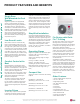
INTRODUCTION “Architectural Appeal” on page 6
ARCHITECTURAL APPEAL Convergence of Technological Innovation with Flexibility and Style Benefits of Single Zone Wall Mounted Art Cool Premier System Single Zone Wall Mounted Art Cool™ Premier Engineering Manual • Available in 9,000, 12,000, 15,000, 18,000, and 24,000 Btu/h • Inverter technology • All-season use - heat pump models for both cooling and heating capabilities • Operating range for outdoor units of 14°F to 118°F (DB) in cooling and -13°F to 65°F (WB) in heating • Operating range for indoor uni
PRODUCT DATA “Product Features and Benefits” on page 8 “Unit Nomenclature” on page 9 “General Data” on page 10 “Electrical Data” on page 13 “Functions, Controls, Options” on page 14 “Outdoor Unit Dimensions” on page 15 “Outdoor Unit Center of Gravity / Corner Weight” on page 17 “Indoor Unit Dimensions” on page 18 “Acoustic Data” on page 20 “Refrigerant Flow Diagrams” on page 22 “Indoor Unit Wiring Diagram” on page 24 “Outdoor Unit Wiring Diagram” on page 26 “Accessories” on page 28
PRODUCT FEATURES AND BENEFITS Single Zone Wall Mounted Art Cool™ Premier Engineering Manual Single Zone Wall Mounted Art Cool Premier Single zone systems are equipped with inverter components that offer superior load matching and long piping installation. The product works for optimizing power consumption in residential and small office buildings. Utilizing multiple indoor wall mount units each with custom temperature controls allow for precise temperature settings in each zone of the building.
UNIT NOMENCLATURE Single Zone Wall Mount Indoor and Outdoor Units LA N 150 HYV 2 Family LA= Art Cool Premier Type N = Indoor Wall Mount Unit U = Outdoor Heat Pump Unit Product Data Nominal Capacity (Nominal cooling capacity in Btu/h) 090 = 9,000 120 = 12,000 150 = 15,000 180 = 18,000 240 = 24,000 Indoor/Outdoor Product HYV = Art Cool Premier Generation or Revision 1 = First 2 = Second Due to our policy of continuous product innovation, some specifications may change without notification.
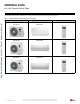
GENERAL DATA Art Cool Premier Pairing Table The following table shows the available outdoor and indoor units, along with the factory provided controller.
GENERAL DATA EEV: Electronic Expansion Valve IDU: Indoor Unit ODU: Outdoor Unit 1 Power Input is rated at high speed. 2 Optional Low Ambient Wind Baffle Kit allows operation down to 0°F in cooling mode. 3 Take appropriate actions at the end of HVAC equipment life to recover, recycle, reclaim or destroy R410A refrigerant according to applicable regulations (40 CFR Part 82, Subpart F) under section 608 of CAA. 4 Sound Pressure levels are tested in an anechoic chamber under ISO Standard 3745.
GENERAL DATA Table 3: Single Zone Wall Mounted Art Cool Premier System Specifications, continued.
ELECTRICAL DATA Table 4: Single Zone Wall Mounted Art Cool Premier System Electrical Data Table. Model Number Nominal Tons Compressor Qty. Compressor (A) Cool/Heat Fan Qty. ODU Fan (A) IDU Fan (A) MCA(A) MOP(A) LA090HYV1 3/4 1 8.3/8.3 1 0.40 0.40 11.2 15 LA120HYV1 1 1 8.3/8.3 1 0.40 0.40 11.2 15 LA150HYV2 1-1/4 1 14.5/14.5 1 0.50 0.3 19.0 25 LA180HYV2 1-1/2 1 14.5/14.5 1 0.50 0.3 19.0 25 LA180HYV1 1-1/2 1 14.5/14.5 1 0.50 0.30 19.
FUNCTIONS, CONTROLS, OPTIONS Table 5: Indoor Units—Functions, Controls and Options.
OUTDOOR UNIT DIMENSIONS LAU090HYV1, LAU120HYV1 4-3/16 1 10-1/2 22 30-5/16 Drain Hole 8-Ø13/16 Sump Heater 10-15/16 Air Discharge Grille Ø17-3/8 13 13-15/16 1/2 Liquid Piping Connection Port Vapor Piping Connection Port Product Data 2-3/4 21-1/2 Control Box 5/8 4-15/16 11-5/16 25° 13/16 25° 9-5/16 12-1/16 6-7/16 5-1/8 2-1/8 1-1/4 Unit: Inch Due to our policy of continuous product innovation, some specifications may change without notification. © LG Electronics U.S.A., Inc.
OUTDOOR UNIT DIMENSIONS LAU150HYV2, LAU180HYV2, LAU180HYV1, LAU240HYV1 6-1/2 Single Zone Wall Mounted Art Cool™ Premier Engineering Manual Unit: Inch 15/16 15-1/8 Sheath Heater 13-1/8 21-1/2 3-3/16 9/16 Vapor Piping Connection Port Liquid Piping Connection Port 5-7/8 6-13/16 6-15/16 25° 14° 7-11/16 12-5/8 1-13/16 4-1/4 13-7/16 14-3/16 Control Box 31-1/2 20-7/8 2-3/4 16 | PRODUCT DATA Due to our policy of continuous product innovation, some specifications may change without notificat
OUTDOOR UNIT CENTER OF GRAVITY / CORNER WEIGHT Figure 1: Center of Gravity and Corner Weight Dimensions Diagram. d D A e c C B Product Data b a Table 6: Center of Gravity and Corner Weight Dimensions. Model LAU090HYV1, LAU120HYV1 LAU150HYV2, LAU180HYV2 LAU180HYV1, LAU240HYV1 Weight (lb.) Shipping Net 81.8 130.1 130.1 76.9 121.3 121.
INDOOR UNIT DIMENSIONS Air Inlet Grille 9-1/4 11-5/8 34-7/16 2-3/16 Front Panel 1-1/8 Knockout Hole 2-3/16 2 2 1-1/16 Display and Signal Receiver 6 1-1/4 2-7/16 1-7/16 2-7/16 1-5/16 1/4 x 1/8 1/8 x 1/4 5/8 PRODUCT DATA 2 Ø2-9/16 Installation Plate 4-13/16 6-15/16 | 17-5/16 Ø2-9/16 Left rear piping 18 17 1 1-7/8 Place a level on raised tab Unit Outline 11-5/8 Single Zone Wall Mounted Art Cool™ Premier Engineering Manual LAN090HYV1, LAN120HYV1 Right rear piping 6-11/16 8-9
INDOOR UNIT DIMENSIONS LAN150HYV2, LAN180HYV2, LAN180HYV1, LAN240HYV1 Air Inlet Grille 42-15/16 2-1/16 2-9/16 13 9-13/16 Front Panel 6 1-1/16 1-7/8 2-3/8 Product Data Display and Signal Receiver 1-1/4 2-7/16 1-7/16 1-5/16 2-7/16 1/4 x 1/8 1/8 x 1/4 5/8 1-7/16 2-3/8 Place a level on raised tab 21-11/16 21-5/16 Ø2-9/16 Left rear piping 2-3/4 7-11/16 Installation Plate Ø2-9/16 1-5/16 Unit Outline 13 1-1/8 Knockout Hole Right rear piping 3-15/16 7-3/16 Due to our policy of continu
OUTDOOR UNIT ACOUSTIC DATA • Measurements are taken 3.28 ft away from the front of the unit. • Sound pressure levels are measured in dB(A) with a tolerance of ±3. • Sound pressure levels are tested in an anechoic chamber under ISO Standard 3745. • Sound level will vary depending on a range of factors including the construction (acoustic absorption coefficient) of a particular room in which the unit was installed.
INDOOR ACOUSTIC DATA Figure 5: Indoor Unit Sound Levels • • • • Measurements are taken 3.28 ft away from the front of the unit. Sound pressure levels are measured in dB(A) with a tolerance of ±3. Sound pressure levels are tested in an anechoic chamber under ISO Standard 3745. Sound level will vary depending on a range of factors including the construction (acoustic absorption coefficient) of a particular room in which the unit was installed.
REFRIGERANT FLOW DIAGRAMS LAU/LAN090HYV1, LAU/LAN120HYV1 Indoor Un it Outdoor Unit Single Zone Wall Mounted Art Cool™ Premier Engineering Manual FIELD PIPIN G (Ø 1/ 4” Co pper Tubing) 2-Way Valve Liqui d Side EEV M TH1 He at Exchanger (Evaporator) TH4 He at Exchanger (Condenser) M TH3 TH2 Reve rsing Va lv e 3- Wa y Valve FI EL D PIPI N G (Ø 3/ 8” Copper Tubing) TH5 Vapor Side TH6 Accumulator : Cooling : Heating Compresso r Thermistor Description PCB Connector TH1 Indoor air tempera
REFRIGERANT FLOW DIAGRAMS LAU/LAN150HYV2, LAU/LAN180HYV2, LAU/LAN180HYV1, LAU/LAN240HYV1 I ndoor Un it Outdoor Unit FIELD PIPI N G (Ø 3/8” Copper Tubing) 2-Way Valve Liqui d Side EEV M TH1 Heat Exchanger (Evaporator) TH4 Heat Exchanger (Condenser) M TH3 TH2 Reve rsing Valve 3- Wa y Valve F IELD PIPI N G (Ø 5/ 8” Coppe r Tubing) TH5 Vapor Side Product Data Th 6 Accumulato r : Cooling : Heating Compresso r Thermistor Description PCB Connector TH1 Indoor air temperature thermistor CN
WIRING DIAGRAM Single Zone Wall Mounted Art Cool™ Premier Engineering Manual LAN090HYV1, LAN120HYV1 24 | PRODUCT DATA Due to our policy of continuous product innovation, some specifications may change without notification. © LG Electronics U.S.A., Inc., Englewood Cliffs, NJ. All rights reserved. “LG ” is a registered trademark of LG Corp.
WIRING DIAGRAM LAN150HYV2, LAN180HYV2, LAN180HYV1, LAN240HYV1 Product Data Due to our policy of continuous product innovation, some specifications may change without notification. © LG Electronics U.S.A., Inc., Englewood Cliffs, NJ. All rights reserved. “LG ” is a registered trademark of LG Corp.
WIRING DIAGRAM Single Zone Wall Mounted Art Cool™ Premier Engineering Manual LAU090HYV1, LAU120HYV1 26 | PRODUCT DATA Due to our policy of continuous product innovation, some specifications may change without notification. © LG Electronics U.S.A., Inc., Englewood Cliffs, NJ. All rights reserved. “LG ” is a registered trademark of LG Corp.
WIRING DIAGRAM LAU150HYV2, LAU180HYV2, LAU180HYV1, LAU240HYV1 Product Data Due to our policy of continuous product innovation, some specifications may change without notification. © LG Electronics U.S.A., Inc., Englewood Cliffs, NJ. All rights reserved. “LG ” is a registered trademark of LG Corp.
ACCESSORIES Single Zone Wall Mounted Art Cool™ Premier Engineering Manual LG Monitoring View (LGMV) Diagnostic Software and Cable LGMV software allows the service technician or commissioning agent to connect a computer USB port to the outdoor unit main printed circuit board (PCB) using an accessory cable without the need for a separate interface device.
PERFORMANCE DATA “Cooling Capacity” on page 30 “Heating Capacity” on page 33 “Maximum Heating Capacity” on page 36 “Air Flow and Temperature Distributions Graphs” on page 39
PERFORMANCE DATA Cooling Capacity LA090HYV1, LA120HYV1 Table 9: LAN090HYV1/LAU090HYV1 Cooling Capacities. Single Zone Wall Mounted Art Cool™ Premier Engineering Manual Outdoor Air 64 / 53 Temp. (°F DB) TC SHC 0 5 7 10 14 23 25 30 35 40 45 50 55 60 65 70 75 80 85 90 95 100 105 110 115 118 122 5.45 5.34 5.38 5.44 5.51 5.92 6.01 6.24 6.47 6.70 6.94 7.17 7.40 7.63 7.56 7.49 7.43 7.36 7.29 7.22 7.15 6.96 6.77 6.59 6.35 6.21 6.02 5.21 5.14 5.18 5.25 5.35 5.74 5.83 6.06 6.28 6.51 6.74 6.96 7.19 7.41 7.34 7.
PERFORMANCE DATA Cooling Capacity LA150HYV2, LA180HYV2 Table 11: LAN150HYV2/LAU150HYV2 Cooling Capacities. Outdoor Air 64 / 53 Temp. TC SHC (°F DB) 9.08 8.91 8.97 9.06 9.18 9.86 10.01 10.40 10.79 11.17 11.56 11.95 12.34 12.72 12.61 12.49 12.38 12.26 12.14 12.03 11.91 11.60 11.29 10.98 10.59 10.35 10.04 7.45 7.35 7.41 7.52 7.65 8.22 8.35 8.67 8.99 9.31 9.64 9.96 10.28 10.60 10.51 10.41 10.31 10.22 10.12 10.03 9.93 9.67 9.41 9.15 8.82 8.63 8.80 0.43 0.45 0.46 0.46 0.47 0.47 0.48 0.52 0.55 0.59 0.62 0.66 0.
PERFORMANCE DATA Cooling Capacity LA180HYV1, LA240HYV1 Table 13: LAN180HYV1/LAU180HYV1 Cooling Capacities. Single Zone Wall Mounted Art Cool™ Premier Engineering Manual Outdoor Air 64 / 53 Temp. (°F DB) TC SHC 0 5 7 10 14 23 25 30 35 40 45 50 55 60 65 70 75 80 85 90 95 100 105 110 115 118 122 11.02 10.81 10.88 10.99 11.14 11.96 12.15 12.62 13.09 13.56 14.03 14.50 14.97 15.44 15.30 15.16 15.02 14.87 14.73 14.59 14.45 14.07 13.70 13.32 12.84 12.56 12.18 8.67 8.55 8.63 8.74 8.90 9.56 9.71 10.08 10.46 10.
PERFORMANCE DATA Heating Capacity LA090HYV1, LA120HYV1 Table 15: LAN090HYV1/LAU090HYV1 Heating Capacities. Outdoor Air Temp. °F DB °F WB -13 -4 -1 0 5 9 14 15 17 23 30 38 40 43 50 53 57 61 65 TC 60 5.08 5.61 6.11 6.38 6.46 6.75 6.96 7.01 7.10 7.79 9.34 10.71 11.06 11.57 11.69 11.96 12.21 12.44 12.62 PI 0.43 0.47 0.52 0.55 0.54 0.56 0.57 0.57 0.58 0.61 0.65 0.70 0.71 0.72 0.73 0.74 0.75 0.76 0.77 TC 64 4.93 5.44 5.92 6.18 6.27 6.54 6.75 6.80 6.89 7.55 9.06 10.39 10.72 11.22 11.34 11.59 11.84 12.
PERFORMANCE DATA Heating Capacity LA150HYV2, LA180HYV2 Table 17: LAN150HYV2/LAU150HYV2 Heating Capacities. Outdoor Air Temp. Single Zone Wall Mounted Art Cool™ Premier Engineering Manual °F DB °F WB -12 -3 0 1 6 10 16 17 19 24 32 41 43 47 53 59 64 70 75 -13 -4 -1 0 5 9 14 15 17 23 30 38 40 43 50 53 57 61 65 Indoor Air Temperature (°F DB/ °F WB) TC 60 8.31 9.18 10.00 10.12 10.58 11.04 11.39 11.47 11.62 12.75 15.28 17.53 18.10 18.94 19.13 19.57 19.98 20.36 20.65 PI 0.84 0.92 1.01 1.02 1.06 1.09 1.
PERFORMANCE DATA Heating Capacity LA180HYV1, LA240HYV1 Table 19: LAN180HYV1/LAU180HYV1 Heating Capacities. Outdoor Air Temp. °F DB °F WB -13 -4 -1 0 5 9 14 15 17 23 30 38 40 43 50 53 57 61 65 TC 60 10.16 11.22 12.22 12.37 12.93 13.50 13.92 14.02 14.21 15.58 18.68 21.43 22.12 23.15 23.38 23.91 24.42 24.89 25.23 PI 1.03 1.13 1.24 1.25 1.29 1.34 1.35 1.36 1.39 1.44 1.56 1.66 1.69 1.73 1.74 1.76 1.79 1.82 1.85 TC 64 9.86 10.88 11.85 12.00 12.53 13.09 13.50 13.59 13.77 15.11 18.11 20.78 21.45 22.45 22.
PERFORMANCE DATA Maximum Heating Capacity LA090HYV1, LA120HYV1 Table 21: LAN090HYV1/LAU090HYV1 Maximum Heating Capacities. Outdoor Air Temp. Single Zone Wall Mounted Art Cool™ Premier Engineering Manual °F DB °F WB -12 -3 0 1 6 10 16 17 19 24 32 41 43 47 53 59 64 70 75 -13 -4 -1 0 5 9 14 15 17 23 30 38 40 43 50 53 57 61 65 Indoor Air Temperature (°F DB/ °F WB) TC 60 7.79 9.82 10.37 10.60 11.48 11.87 12.12 12.21 12.26 13.83 16.33 19.14 19.77 21.03 21.58 21.85 22.02 22.10 22.04 PI 1.01 1.06 1.07 1.
PERFORMANCE DATA Maximum Heating Capacity LA150HYV2, LA180HYV2 Table 23: LAN150HYV2/LAU150HYV2 Maximum Heating Capacities. Outdoor Air Temp. °F DB °F WB -13 -4 -1 0 5 9 14 15 17 23 30 38 40 43 50 53 57 61 65 TC 60 14.54 17.06 17.84 18.17 19.33 20.25 21.33 21.49 21.94 23.05 24.19 25.26 25.49 25.80 26.39 26.68 26.87 26.95 26.89 PI 1.94 2.03 2.05 2.07 2.12 2.13 2.15 2.16 2.17 2.18 2.12 2.00 1.92 1.86 1.89 1.86 1.82 1.75 1.62 TC 64 14.59 16.98 17.74 18.05 19.18 20.08 21.13 21.29 21.73 22.84 23.96 25.
PERFORMANCE DATA Maximum Heating Capacity LA180HYV1, LA240HYV1 Table 25: LAN180HYV1/LAU180HYV1 Maximum Heating Capacities. Outdoor Air Temp. Single Zone Wall Mounted Art Cool™ Premier Engineering Manual °F DB °F WB -12 -3 0 1 6 10 16 17 19 24 32 41 43 47 53 59 64 70 75 -13 -4 -1 0 5 9 14 15 17 23 30 38 40 43 50 53 57 61 65 Indoor Air Temperature (°F DB/ °F WB) TC 60 13.48 16.99 17.95 18.35 20.37 21.44 22.43 22.68 22.96 24.49 26.94 29.69 30.31 31.55 32.36 32.78 33.04 33.15 33.07 PI 2.12 2.21 2.24 2.
PERFORMANCE DATA Air Flow and Temperature Distribution Graphs LAN090HYV1 Cooling Air Velocity [m/s (ft./s)] Temperature [°C (°F)] 5 (16.4) 0.3(1) 1(3.3) 0.5(1.6) m 10 8 6 4 2 0 ft. 32.8 26.2 19.7 13.1 6.6 0 m 2 ft. 6.6 1 3.3 0 0 24(75) 30(86) 16(61) 26(79) 28(82) m 10 8 6 4 2 0 ft. 32.8 26.2 19.7 13.1 6.6 0 m 2 f t. 6.6 1 3.3 0 0 Air Velocity [m/s (ft./s)] 0.3(1) 0.5(1.6) 10 32.8 8 26.2 6 19.7 ft. 16.4 4 13.1 3 9.8 2 1(3.3) m ft. m 5 4 13.
PERFORMANCE DATA Air Flow and Temperature Distribution Graphs LAN090HYV1, continued. Heating Single Zone Wall Mounted Art Cool™ Premier Engineering Manual Air Velocity [m/s (ft./s)] Temperature [°C (°F)] 6 (19.7) 0.3(1) 0.5(1.6) 1(3.3) m 10 8 6 4 2 0 ft. 32.8 26.2 19.7 13.1 6.6 0 m 2 ft. 6.6 1 3.3 0 0 22(72) m f t. 6.6 1 3.3 0 0 34(93) 2 28(82) 26(79) 24(75) m 10 8 6 4 2 0 ft. 32.8 26.2 19.7 13.1 6.
PERFORMANCE DATA Air Flow and Temperature Distribution Graphs LAN120HYV1 Cooling Air Velocity [m/s (ft./s)] Temperature [°C (°F)] 5 (16.4) 0.3(1) 1(3.3) 0.5(1.6) m 10 8 6 4 2 0 ft. 32.8 26.2 19.7 13.1 6.6 0 m 2 ft. 6.6 1 3.3 0 0 24(75) 30(86) 16(61) 26(79) 28(82) m 10 8 6 4 2 0 ft. 32.8 26.2 19.7 13.1 6.6 0 m 2 f t. 6.6 1 3.3 0 0 Air Velocity [m/s (ft./s)] 0.3(1) 0.5(1.6) 10 32.8 8 26.2 6 19.7 ft. 16.4 4 13.1 3 9.8 2 1(3.3) m ft. m 5 4 13.
PERFORMANCE DATA Air Flow and Temperature Distribution Graphs LAN120HYV1, continued. Heating Single Zone Wall Mounted Art Cool™ Premier Engineering Manual Air Velocity [m/s (ft./s)] Temperature [°C (°F)] 6 (19.7) 0.3(1) 0.5(1.6) 1(3.3) m 10 8 6 4 2 0 ft. 32.8 26.2 19.7 13.1 6.6 0 m 2 ft. 6.6 1 3.3 0 0 22(72) m f t. 6.6 1 3.3 0 0 34(93) 2 28(82) 26(79) 24(75) m 10 8 6 4 2 0 ft. 32.8 26.2 19.7 13.1 6.
PERFORMANCE DATA Air Flow and Temperature Distribution Graphs LAN150HYV2, LAN180HYV1 Cooling Air Velocity [m/s (ft./s)] Temperature [°C (°F)] 6.5 (21.3) 1.5(4.9) 0.3(1) 0.5(1.6) 0.3(1) 1(3.3) m 10 8 6 4 2 0 ft. 32.8 26.2 19.7 13.1 6.6 0 m 2 ft. 6.6 1 3.3 0 0 m f t. 6.6 1 3.3 0 0 16(61) 2 22(72) 26(79) 28(82) 30(86) m 10 8 6 4 2 0 ft. 32.8 26.2 19.7 13.1 6.6 0 Air Velocity [m/s (ft./s)] 0.3(1) 0.5(1.6) 1(3.3) m ft. 10 32.8 8 26.2 6 19.7 2(6.6) 4 13.
PERFORMANCE DATA Air Flow and Temperature Distribution Graphs LAN150HYV2, LAN180HYV1, continued. Heating Single Zone Wall Mounted Art Cool™ Premier Engineering Manual Air Velocity [m/s (ft./s)] Temperature [°C (°F)] 6.5 (21.3) 0.3(1) 0.5(1.6) 1.5(4.9) 1(3.3) m 10 8 6 4 2 0 ft. 32.8 26.2 19.7 13.1 6.6 0 m 2 ft. 6.6 1 3.3 0 0 m f t. 6.6 38(100) 2 30(86) 26(79) 1 26(79) 22(72) 24(75) m 10 8 6 4 2 0 ft. 32.8 26.2 19.7 13.1 6.6 0 3.
PERFORMANCE DATA Air Flow and Temperature Distribution Graphs LAN240HYV1 Cooling Air Velocity [m/s (ft./s)] Temperature [°C (°F)] 0.5(1 .6) 6.5 (21.3) ) 2(6.6 0.5(1.6) 0.3(1) 1(3.3) m 10 8 6 4 2 0 ft. 32.8 26.2 19.7 13.1 6.6 0 m 2 ft. 6.6 1 3.3 0 0 30(86) 14(57) 22(72) 24(75) 26(79) 28(82) m 10 8 6 4 2 0 ft. 32.8 26.2 19.7 13.1 6.6 0 m 2 f t. 6.6 1 3.3 0 0 Air Velocity [m/s (ft./s)] 0.3(1) 0.5(1.6) 1(3.3) m ft. 10 32.8 8 26.2 6 19.7 2(6.6) 4 13.
PERFORMANCE DATA Air Flow and Temperature Distribution Graphs LAN240HYV1, continued. Single Zone Wall Mounted Art Cool™ Premier Engineering Manual Heating Air Velocity [m/s (ft./s)] Temperature [°C (°F)] 7(23) 0.3(1) 0.5(1.6) 1(3.3) 2(6.6) 1.5(4.9) m 10 8 6 4 2 0 ft. 32.8 26.2 19.7 13.1 6.6 0 m 2 ft. 6.6 1 3.3 0 0 40(104) 32(90) 28(82) 26(79) 24(75) m 10 8 6 4 2 0 ft. 32.8 26.2 19.7 13.1 6.6 0 m 2 f t. 6.6 1 3.
APPLICATION GUIDELINES “Equipment Selection Procedure” on page 48 “Building Ventilation Design Guide” on page 49 “Placement Considerations” on page 51
EQUIPMENT SELECTION PROCEDURE Cooling/Heating Correction Factors Single Zone Wall Mounted Art Cool™ Premier Engineering Manual For Single Zone Art Cool Premier systems, calculate the equivalent length of the liquid line from the outdoor unit to the indoor unit. Also, determine the elevation difference of the indoor unit above or below the outdoor unit. Find corresponding cooling or heating capacity correction factors as shown in the table below.
BUILDING VENTILATION DESIGN GUIDE Building Ventilation Design Guide ASHRAE 62.1 and local codes specify the minimum volume of outdoor air that must be provided to an occupied space. Outdoor air is required to minimize adverse health effects, and it provides acceptable indoor air quality for building occupants. The three methods of accomplishing this with single zone systems are summarized here.
BUILDING VENTILATION DESIGN GUIDE Method 2: Unconditioned Outdoor Air (Non-Ducted, Natural Ventilation) Natural ventilation devices, such as operable windows or louvers may be used to ventilate the building when local code permits. The open area of a window or the free area of a louver must meet the minimum percentage of the net occupied floor area. Single Zone Wall Mounted Art Cool™ Premier Engineering Manual Advantages • Occupants control the volume of the ventilation air manually.
PLACEMENT CONSIDERATIONS Selecting the Best Location DANGER To avoid the possibility of fire, do not install the unit in an area where combustible gas may generate, flow, stagnate, or leak. Failure to do so will cause serious bodily injury or death. Install a fence to prevent vermin from crawling into the unit or unauthorized individuals from accessing it. where acidic solution and spray (sulfur) are often used as this may cause serious bodily injury or death.
PLACEMENT CONSIDERATIONS Indoor Unit Clearance/Outdoor Unit Installation Single Zone Wall Mounted Art Cool™ Premier Engineering Manual Indoor Unit Best Location Figure 11: Single Zone Indoor Unit Clearance Requirements. Follow recommended best practices when choosing an indoor location for the single zone indoor unit. • Use a metal detector to locate studs in the walls. Anchor unit following stud location, to prevent damage to the wall.
PLACEMENT CONSIDERATIONS Outdoor Unit Clearances Minimum Clearance Requirements for Single Zone Art Cool Premier Systems Proper clearance for the outdoor unit coil is critical for proper unit operation. When installing the outdoor unit, consider service, inlet and outlet and minimum allowable space requirements as illustrated in the diagrams below. Specific clearance requirements in the diagram below are for the Single Zone Wall Mounted Art Cool Premier systems.
REFRIGERANT PIPING DESIGN & LAYOUT BEST PRACTICES “Refrigerant Piping Design” on page 55 "Selecting Field-Supplied Copper Tubing" on page 56 "Refrigerant Piping System Layout" on page 57 "Electrical Connections" on page 61
REFRIGERANT PIPING DESIGN Design Guideline Summary/Selecting Field-Supplied Copper Tubing Device Connection Limitations Single-zone systems consist of one outdoor unit and one indoor unit. One of the most critical elements of a single zone system is the refrigerant piping. The table below lists pipe length limits that must be followed in the design of a Single Zone Wall Mounted Art Cool Premier refrigerant pipe system. Refer to the figure for maximum length and elevation of piping.
REFRIGERANT PIPING DESIGN Selecting Field-Supplied Copper Tubing Single Zone Wall Mounted Art Cool™ Premier Engineering Manual Table 31: Linear Thermal Expansion of Copper Tubing in Inches. Pipe Length1 10 20 30 40 50 60 1 35° 0.04 0.08 0.12 0.16 0.20 0.24 40° 0.04 0.08 0.12 0.16 0.20 0.24 45° 0.05 0.10 0.15 0.20 0.25 0.30 50° 0.06 0.12 0.18 0.24 0.30 0.36 55° 0.06 0.13 0.20 0.26 0.33 0.39 60° 65° 0.07 0.14 0.21 0.28 0.35 0.42 70° 0.08 0.15 0.23 0.30 0.38 0.45 0.08 0.16 0.24 0.32 0.40 0.
INSTALLATION & LAYOUT BEST PRACTICES Refrigerant Piping System Layout Field-Provided Isolation Ball Valves Obstacles 3X When an obstacle, such as an I-beam or concrete T, is in the path of the planned refrigerant pipe run, it is best practice to route the pipe over the obstacle. If adequate space is not available to route the insulated pipe over the obstacle, then route the pipe under the obstacle.
INSTALLATION & LAYOUT BEST PRACTICES Refrigerant Piping System Layout Pipe Sleeves at Penetrations LG requires that all pipe penetrations through walls, floors, and pipes buried underground be properly insulated and routed through an appropriate wall sleeve of sufficient size to prevent compression of refrigerant pipe insulation and free movement of the pipe within the sleeve. Underground refrigerant pipe shall be routed inside a protective sleeve to prevent insulation deterioration See figure below.
INSTALLATION & LAYOUT BEST PRACTICES Refrigerant Piping System Layout Single Zone Art Cool Premier Outdoor Unit Connections 1. Remove the tubing cover from the unit by loosening the fastening screws. 2. Align the center of the refrigerant pipe and corresponding connection. 3. Place a couple of drops of refrigerant oil on the opening rim of the flare before assembling. add any contaminants. Tighten the flare nut initially by hand. 4.
INSTALLATION & LAYOUT BEST PRACTICES Refrigerant Piping System Layout Refrigerant Piping / Brazing Practices Single Zone Wall Mounted Art Cool™ Premier Engineering Manual It is imperative to keep the piping system free of contaminants and debris such as copper burrs, slag, or carbon dust during installation. All joints are brazed in the field. Single Zone Wall Mounted Art Cool Premier Figure 27: Refrigerant Pipe Brazing.
ELECTRICAL CONNECTIONS Outdoor Electrical Connection Figure 29: LAU150HYV2/ LAU180HYV2, LAU180HYV1/ LAU240HYV1 Outdoor Unit Electrical Connection. Terminal Block 1(L1) 2(L2) Terminal Block Connecting Cable Over 0.2” Power Supply Cord Power Supply Cord Conduit Panel Conduit Panel Connecting Cable Terminal Cover Tubing Cover • Separately wire the high and low voltage lines. There is a risk of electric shock, physical injury, or death.
TECHNICAL DATA “Mechanical Specifications” on page 63 “Acronyms” on page 64
MECHANICAL SPECIFICATIONS Single Zone Wall Mounted Art Cool Premier General Temperature Ranges Outdoor Unit Operating ranges for Outdoor units of 14°F to 118°F DB for cooling; -13°F to 65°F WB for heating. Indoor Unit Operating ranges for Indoor Units of 53°F to 75°F WB for cooling; 60°F to 86°F DB for heating. (Installing an optional Low Ambient Wind Baffle Kit will allow operation down to 0°F in cooling mode for these single zone systems.
ACRONYMS Single Zone Wall Mounted Art Cool™ Premier Engineering Manual Table 38: Table of Acronyms.
20001747 ISO 9001: 2008 LG ELECTRONICS INC. LG Electronics, U.S.A., Inc. Commercial Air Conditioning Division 4300 North Point Parkway Alpharetta, Georgia 30022 www.lg-dfs.com LG Electronics Commercial Products Support 1-888-865-3026 USA Follow the prompts for commercial A/C products.