LG Ceiling Duct-Type Air Conditioner LG OWNER'S MANUAL IMPORTANT Please read through this manual. It contains valuable information about your air conditioner. This manual may help save time and money by explaining proper product maintenance and preventing improper use. PRECAUTIONS Pay close attention to precautions in order to prevent potential hazards and damage from misuse or improper installation. LG is not responsible for any damages caused by misuse of the product. LG Electronics India Pvt. Ltd.
Ceiling Duct-Type Air Conditioner Owner’s Manual TABLE OF CONTENTS F or Your Records Write the model and serial numbers here: Model # Serial # 1. Safety Precautions You can find them on a label on the side of each unit. 2. Operating Instructions Dealer's Name 3. Care and Maintenance Date Purchased 4. Before you call for service R ead This Manual Inside you will find many helpful hints on how to use and maintain your air conditioner properly.
Safety Precautions Precautions To prevent injury and property damage, follow these instructions. Incorrect operation due to ignoring instructions will cause harm or damage, the seriousness of which is indicated by the following symbols. WARNING This symbol shows the possibility of death or serious injury. CAUTION This symbol indicates the possibility of injury or damage to property.
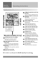
Operating Instructions Operating Instructions Name and Function of Remote Controller OPERATION MODE SELECTION BUTTON Used to select the operation mode.
Installer Setting Code Table 1) General air-conditioner product No. 1 2 Function Test Run Address Setting Code 01 02 3 E.S.P. Value 03 4 Thermistor 04 5 Ceiling Height 05 6 Static Pressure 06 7 Master Setting 07 8 Override Setting 08 9 Dry Contact 09 10 Release 3 Min.
Owner's instruction Standard Operation - Standard Cooling It cools the room by comfortable and clean air. 1 Press indoor. button to turn on the button to select 2 Press Cooling operation mode. the desired temperature 3 Adjust by pressing buttons. Press button to check the Room temperature.
Standard Operation - Power Cooling (Optional) Power cooling can be used to cool the room quickly in hot summer. 1 Press indoor. button to trun on the button to select 2 Press cooling operation mode. button continuously 3 Press until 'Po' displayed. What is Power Cooling? • Desired temperature: Po (actually 18°C) • Wind flow: power wind • Wind direction: fix to air-cooling position } It make room temperature drop fast by running Partial product has no power air-cooling function.
Standard Operation - Dehumidification Mode This mode dehumidification without overcooling. 1 Press indoor. button to turn on the button to select 2 Press Dehumidification mode. The temperature setting can not be adjusted during operation this mode. the in order of low 3 Press medium high (The initial wind powerfulness of humidity removal drive is 'low'.) • In rainy season or high humidity climate, it is possible to operate simultaneously dehumidifier and cooling mode to remove humidity effectively.
Standard Operation - Auto Operation Mode 1 Press indoor. button to turn on the button to select 2 Press Artificial intelligence Mode. can adjust 3 You the temperature as the picture on the right for cooling and heating model. the case of 4 For cooling exclusive, as the picture on the right, you can adjust the temperature from hot to cold, from "-2" to "2" based on "00". During operating Auto Operation mode : • We can use the FAN SPEED button • We can change manually to other operation mode.
Standard Operation - Temperature Setting/Room Temperature Check Temperature Setting can simply adjust the desired 1 We temperature. • Press the buttons to adjust the desired temperature. : Increase 1°C or 2°F per one time pressing : Decrease 1°C or 2°F per one time pressing • Room temp: Indicate the current room temperature. • Set temp: Indicate the temperature that user want to set. Depend on what kind of controller, the desired temperature can be adjusted at 0.5°C or 1°F.
Sub function - Energy-Saving Cooling Operation (Optional) Power saving air-cooling function is the function to improve use's comfortableness and power saving capacity by adjusting desired temperature while running air-cooling pressing 1 Repeatedly until icon flash. button or cancel Energy-Saving 2 Operate function by pressing button. (To cancel power saving function, you move to power saving menu by pressing button, and then if pressing button, power saving icon disappears and the function is cancelled.
Function setting - Child Lock It is the function to use preventing children or others from careless using. button repeatedly until 1 Press the is flashing. moving to 'setup' icon area by 2 Ifusing button, 'setup' icon blinks, and child lock function is setup if pressing button at that time. cancelling lock function, if moving 3 When to 'cancel' icon by pressing button and then, pressing button, child lock function is cancelled. button to exit.
Function setting - Current Time This Procedure sets the current time and day of the week. press function setup 1 Please button. If pressing function setup button repeatedly, it moves to time setup menu. ‘Time setup’ icon is indicated at that time and date blinks at current time indication area. Ex) Changing Current Time as 'Monday / AM 10:20'. 2 Press day. key to adjust the current key to move to AM/ PM setting 3 Press mode (the 'AM/ PM segment will flash). AM/ PM value by 4 Setting pressing button.
button to move to 'Minute' 7 Press setting mode. (the 'Minute' segment will flash) Minute value by pressing 8 Setting button. 9 Press 10 20 button to finish. In the process, press button to release and exit from setting mode. (In case of exit with incomplete information, it will return to the previous setting) When exiting without pressing set button, the manipulated value is not reflected.
Programming - Simple Reservation You can set the reservation conveniently in the units of 1 hour from 1 hour to 7 hours. button to enter the 1 Press Programming mode. (the segment flashing) Ex) Setting Simple Reservation time as '3'. 2 Press time. 3 Press button to adjust reservation button to finish setting. button to exit. 4 Press After setup, it automatically gets out of setup mode if there is no button input for 25 seconds.
Programming - Sleep Reservation Sleep reservation is the function of air-conditioner to run and stop after certain period of time at sleep mode before sleep. button to enter the 1 Press Programming mode. Ex) Setting Sleep Reservation time as '3'. pressing button to enter the 2 Repeat SLEEP reservation setting mode. ( segment flashing) 3 Press time. button to adjust reservation The SLEEP reservation time is from 1 to 7 hours. button to finish setting. 4 Press Whenever reservation is done.
Programming - ON Reservation Automatically turned On at reserved time that you set. 1 Press button. Ex) Setting ON Reservation Time as 'AM 10:20'. pressing button to 2 Repeat enter the ON reservation setting mode. ( segment flashing) 3 Press setting. button to adjust AM/ PM button to Hour setting 4 Press mode. When the Hour icon flash, please setting time. The setting range is within 1~12. button to shift to Minute 5 Press setting mode.
button to exit. 7 Press After setup, it automatically gets out of setup mode if there is no button input for 25 seconds. When exiting without pressing set button, the manipulated value is not reflected. - If reservation is set, 'turned on' indication shows up at the lower part of LCD screen, and air-conditioner product runs at the time that is set. - If reservation is cancelled, 'turned on' indication disappears.
Programming - OFF Reservation Automatically turned Off at reserved time that you set. 1 Press button. Ex) Setting OFF Reservation Time as 'AM 10:20'. pressing button 2 Repeatedly to enter the OFF reservation setting mode. ( segment flashing) 3 Press setting. button to adjust AM/ PM button to shift to Hour 4 Press setting mode. When the Hour icon flash, please setting time. The setting range is within 1~12. button to shift to Minute 5 Press setting mode.
button to exit. 7 Press After setup, it automatically gets out of setup mode if there is no button input for 25 seconds. When exiting without pressing set button, the manipulated value is not reflected. - If reservation is set, 'turned off' indication shows up at the lower part of LCD screen, and air-conditioner product runs at the time that is set. - If reservation is cancelled, 'turned off' indication disappears.
Programming : Weekly Reservation This function is used to program the unit for the specified running during the week. 1 Please move to reservation setup mode by pressing reservation button. You can setup two weekly reservations for one day, and up to fourteen reservations for a week. For example, to setup (Tuesday morning 11:30 turned on ~ afternoon 12:30 turned off), you setup in order below. move to 'weekly' by 2 Please repeatedly pressing reservation button. 'Weekly' blinks at this time.
move to 'AM/PM' setup part 10 Please of turning off by using button. - AM/PM setup is identical with turning on time setup. 11 Please move to 'hour' setup part of turning off by using Right button. - It is the part to reserve the time at which air-conditioner is turned off. - If 'hour' indication blinks, please setup 'hour'. Please setup 'hour' and 'minute' identically with the method to setup turning on time. finishing weekly reservation setup, please press setup/cancellation button.
Programming : Holiday Reservation This function automatically stop the machine on the set day press button. 1 Please It enters into reservation setup mode. move to 'holiday' by repeatedly 2 Please pressing button. move to 'date' that 3 Please you want to setup holiday by using button. cancel holiday by using 4 Pleaseorset orbutton. For example, when you setup Monday/Friday to holiday - 'Monday', 'Friday' letter disappears. press 5 Please holiday setup.
Installer Setting - Setting Address of Central Control This procedure is used to set up the address of Indoor units. Please refer to central controller manual for connecting Indoor units with the control controller pressing button long for 3 1 Ifseconds, it enters into remote controller setter setup mode. - If pressing once shortly, it enters into user setup mode. Please press more than 3 seconds for sure. into address setup mode by using 2 If entering button, it indicates as picture below. Indoor No.
The Room Temperature Confirmation Function setting - 3 Compressor Selection It is the function for adjusting the number of running outdoor Units linked a indoor unit. 1 Repeat Pressing Button until Icon ON 2 Press button to change. Converting comp value : 1~3 3 Press button to complete and active the setting process 4 Press button to exit or system will automatically release without any input after 25 seconds. When exiting without pressing set button, the manipulated value is not reflected.
Pressure Function Sr. No. * KEY & MODE OPERATION ERROR RESET Low Pressure Function (LP Operation) – When Low Pressure operates, it stops Comp as well as O/D Unit after 10 sec of Comp Operation. Respective Comp No. will blink. Blinking Zone 1 2 3 Manual power reset. Respective Comp No. will blink. Blinking Zone 1 2 3 Manual power reset. – If Comp Off occurs 3 times in 1 hour by L/P operation after the first detection, Comp Off state has been maintained.
Operation Details • Cooling Operation Mode When the room temperature is higher than the set temperature, it operates in cooling mode at the set temperature, the set fan speed, and then it will be in automatically turn off when the room temperature reaches the set temperature +0.5¡C. ROOM TEMP. More 3 minutes OPERATION START SET TEMP. +0.5°C) OPERATION STOP SET TEMP. -0.
Care and maintenance Care and maintenance Caution: Before performing any maintenance, turn off the main power to the system. Indoor Unit Grille, Case, and Remote Control: q Turn the system off before cleaning. To clean, wipe with a soft, dry cloth. Do not use bleach or abrasives. Note: Supply power must be disconnected before cleaning the indoor unit. q Never use any of the followings: • Water hotter than 40°C Could cause deformation and/or discoloration.
Outdoor Unit The heat exchanger coils and panel vents of the outdoor unit should be checked regularly. If clogged with dirt or soot, the heat exchanger and panel vents may be professionally steam cleaned. Note: Dirty or clogged coils will reduce the operating efficiency of the system and cause higher operating costs.
7. Air Purging of the Connecting Pipes and the Indoor Unit The air which contains moisture remaining in the refrigeration cycle may cause a malfunction on the compressor. 1. Confirm that both the liquid side valve and the gas side valve are set to the closed position. 2. After connecting the piping, check the joints for gas leakage with gas leak detector. 3. Remove the service port nut, and connect the gauge manifold and the vacuum pump to the service port by the charge hose. 4.
4) Form the pipings 1. Wrap the connecting portion of indoor unit with the Insulation material and secure it with two Plastic Bands. (for the right pipings) Seal a small opening around the pipings with gum type sealer. • If you want to connect an additional drain hose, the end of the drain-outlet should keep distance from the ground. (Do not dip it into water, and fix it on the wall to avoid swinging in the wind.) In case of the Outdoor unit being installed below position of the Indoor unit.
3) Connecting the cable to the Outdoor Unit Outdoor unit Terminal block 1. Remove the Cover control from the unit by loosening a screw. Connect the wires to the terminals on the control board individually as following. 2. Secure the cable onto the control board with the holder (clamper). Cord Clamper Over 5mm 3. Refix the cover control to the original position with the screw.
6. Connecting Cables between Indoor and Outdoor Unit 1) Connecting cables to the Indoor Unit Connect the wires to the terminals on the control board individually according to the outdoor unit connection. Ensure that the color of the wires of outdoor unit and the terminal No. are the same as those of indoor unit respectively. Please do the interconnection as per Interconnection Table in wiring diagram.
Wiring Diagram Unit : 264K BTU/H CONTROL BOX WIRING DIAGRAM In door & control box connection detail CONTROL BOX Terminal No. N L3 L2 L1 3ø MONITORING RELAY 18 15 R Y B N R Y B N DRY CONTACT WIRED REMOTE CONTROLLER PHASE IN ( R ) PHASE IN ( Y ) PHASE IN ( B ) NEUTRAL IN IDM PHASE (R) IDM PHASE (Y) IDM PHASE (B) IDM PHASE T.O.P. IDM PHASE T.O.P. 1 2 3 4 5 6 7 INDOOR 3Ø415 V POWER SUPPLY 1 2 3 4 5 TP TP IDM PHASE (R) IDM PHASE (Y) IDM PHASE (B) IDM PHASE T.O.P. IDM PHASE T.O.P.
Wiring Diagram Unit : 198K BTU/H CONTROL BOX WIRING DIAGRAM R R Y R Y B Y B B N R Y B N R Y BN In door & control box connection detail CONTROL BOX Terminal No. R Y B N N N L1 L2 L3 3ø MONITORING RELAY 18 15 R Y B N DRY CONTACT WIRED REMOTE CONTROLLER PHASE IN ( R ) PHASE IN ( Y ) PHASE IN ( B ) NEUTRAL IN IDM PHASE (R) IDM PHASE (Y) IDM PHASE (B) IDM PHASE T.O.P. IDM PHASE T.O.P.
Wiring Diagram Unit : 132K BTU/H (1 ODU - Single Piping) In door & Out door connection detail COMP(1) L1 OUTDOOR WIRING DIAGRAM L3 MOTOR GREY R 2 C S MOTOR R 1C S 15 18 25 28 3ø MONITORING RELAY A2 L1 L2 L3 A1 CAPACITOR 2 9 10 LP1/HP1 LP1/HP1 CAPACITOR 1 OUTDOOR Terminal No.
Wiring Diagram Unit :132K BTU/H (2 ODU) In door & Out door connection detail OUTDOOR WIRING DIAGRAM COMP.1 T1 BLACK T3 C2R S 1 CS R MOTOR MOTOR YELLOW ORANGE T2 COMP.
Wiring Diagram Unit : 132K BTU/H OUTDOOR WIRING DIAGRAM COMP(1) COMP(2) In door & Out door connection detail W OUT(A) MOTOR BK U TERMINAL (C) 21 21 BL BL 28 25 RD 18 15 20 W V U V OUT(B) MOTOR BK BK BK 14 13 INDOOR BK WH RD BK WH RD L3 L2 L1 RD 7 L1 L2 L3 A2 A1 Magnetic A Contactor BK T1 T2 T3 BL YL RD L1 L2 L3 A2 A1 OUTDOOR Terminal No.
Wiring Diagram Unit : 102K BTU/H(1 ODU - Single Piping) OUTDOOR WIRING DIAGRAM In door & Out door connection detail INDOOR OUTDOOR Terminal No. COMP.
Wiring Diagram Unit :102K BTU/H OUTDOOR WIRING DIAGRAM COMP(1) COMP(2) In door & Out door connection detail INDOOR W BR 7 U W V U MOTOR 1 R C S MOTOR 2 R YELLOW C S ORANGE 21 21 BL BL 28 25 RD 18 15 20 RD 20 BK WH RD BK WH RD 1 2 3 4 5 6 PHASE IN ( R ) PHASE IN ( Y ) PHASE IN ( B ) NEUTRAL IN GND IN NC 1 7 PHASE 2 8 NEUTRAL 9 GND 10 7 COMP1 11 8 COMP2 3 4 5 IN door motor 6 L3 L2 L1 CAPACITOR 2 6 5 4 BL YL RD A1 Magnetic 1 Contactor BK T1 T2 T3 BL YL RD BK 11 3 PHASE NEUTRAL C/B B
Wiring Diagram Unit : 90K BTU/H (1 ODU - Single Piping) OUTDOOR WIRING DIAGRAM In door & Out door connection detail INDOOR OUTDOOR Terminal No. COMP.
Wiring Diagram Unit : 90K BTU/H OUTDOOR WIRING DIAGRAM COMP(1) W BR 7 U W V COMP(2) U V In door & Out door connection detail INDOOR MOTOR 1 R C S MOTOR 2 C R YELLOW S 21 21 BL BL 28 25 RD 18 15 20 RD 20 BK WH RD BK WH RD 3ø MONITORING RELAY CAPACITOR 2 6 5 4 BL YL RD A1 Magnetic 1 Contactor BK 11 L1 L2 L3 A2 A1 Magnetic 2 Contactor 11 11 T1 T2 T3 BK 9 8 7 BK BL YL RD LP/HP1 LP/HP1 LP/HP2 LP/HP2 9 10 11 12 PHASE IN ( R ) PHASE IN ( Y ) PHASE IN ( B ) NEUTRAL IN GND IN NC 13 14 15
Wiring Diagram Unit : 51K / 66K BTU/H OUTDOOR WIRING DIAGRAM COMP.
T2 COMP. R 1 T1 RD WH BK S 2 RD YL BL T2 T1 T2 L1 L2 L3 A2 MAGNETIC CONTACTOR T3 A1 T3 BK RD 18 15 N 8 1 BK 3ø 415V POWER SUPPLY T 3 TERMINAL A N YELLOW 10 S 11 ORANGE MOTOR 9 GR/YL L BLACK G RD 7 3ø MONITORING RELAY L3 L2 L1 TERMINAL B TERMINAL A BK RD T3 A1 BL 3 N G 7 RD 8 RD BL YL RD OUTDOOR WIRING DIAGRAM DRY CONTACT L N 9 BK BK COMP.
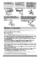
4. Connecting Pipes to the Outdoor Unit 1) Connecting the pipes to the Outdoor unit 1. Align the center of the pipingsand sufficientlytighten the flare nut with fingers. 2. Finally, tightenthe flare nut with torque wrenchuntilthe wrenchclicks. • When tightening the flare nut with torque wrench, ensure the direction for tightening follows the arrow on the wrench. 4.2kg.m 3/8" 1.8kg.m 1/4" Torque Pipe size 6.6kg.m 3/4" 6.6kg.m 5/8" 5.5kg.m 1/2" Outdoor unit Gas side piping (Bigger Dia.
6) Pipe bending Annealed copper pipe with small diameter (ø6.35 or ø9.52) can be easily bent manually. In this case, secure large R(radius) for the bend section and gradually bend pipe. If annealed copper pipe is large in diameter (ø12.7, ø15.88 or ø19.05), bend pipe with bender. Use bender appropriate for the pipe diameter. 7) Brazing In refrigerant piping, bending (in particular, acute bending) must be minimized to reduce piping resistance.
3. Connecting Pipes to the Indoor Unit 3-1. Preparation of Piping Main cause of gas leakage is defect in flaring work. Carry out correct flaring work in the following procedure. Copper tube 90➀ Slanted Uneven Rough 1) Cut the pipes and the cable. nUse the accessory piping kit or the pipes purchased locally. nMeasure the distance between the indoor and the outdoor unit. nCut the pipes a little longer than measured distance. nCut the cable 1.5m longer than the pipe length.
ELECTRICALWIRING Perform the electrical wiring work according to the electrical wiring connection. • All wiring must comply with local requirements. • Select a power source that is capable of supplying the current required by the air conditioner. • Use a recognized circuit breaker between the power source and the unit. A disconnection device to adequately disconnect all supply lines must be fitted.
REFRIGERANT PIPING Perform the work according to the Service Manual or Installation Guide. • Braze the joints • Perform air purge with R-22 or vacuum drying. Factory charged gas Braze the connection pipes • When piping work is finished, check all joints. n Add refrigerant if piping is over 7.5m. Use hard pipe Outdoor U-Trap (See page 4 for details) • U-trap is to be provided for every 5 mtr. increase in the vertical length of the pipe.
INSTALLATION OF REMOTE CONTROL BOX Install the remote control box and cord correctly. POINT OF REMOTE CONTROLLER INSTALLATION • Although the room temperature sensor is in the indoor unit, the remote control box should be installed in such places away from direct sunlight and high humidity. • Keep the remote control cord away from the refrigerant piping and the drain piping. • To protect the remote control cord from electrical noise, place the cord at least 5cm away from other power cables.
• For every 5 mitrs. increase in vertical length of the piping, U-Trap is to be provided.
lDrill the piping hole with 70mm dia, hole core drill. lPiping hole should be slightly slant to the outdoor side. Indoor WALL Outdoor 5~7mm INSULATION, OTHERS THERMAL INSULATION Insulate the joint and tubes completely. All thermal insulation must comply with local requirement.
CAUTION 1. Install declination of the indoor unit is very important for the drain of the duct type air conditioner. 2. Minimum thickness of the insulation for the connecting pipe shall be 5mm. Front of view • The unit must be horizontal or declined to the drain hose connected when finished installation. Ceiling 5~8mm CORRECT INCORRECT Drainage hole CAUTION FOR GRADIENT OF UNIT AND DRAIN PIPING Drainage hole Lay the drain hose with a downward inclination so water will drain out.
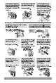
• Select and mark the position for fixing bolts. • Drill the hole for set anchor on the face of ceiling. • Insert the set anchor and washer onto the suspension bolts for locking the suspension bolts on the ceiling. • Mount the suspension bolts to the set anchor firmly. • Secure the installation plates onto the suspension bolts (adjust level roughly) using nuts, washers and spring washers.
2. Indoor unit installation nInstallation of Unit Install the unit above the ceiling correctly. A B POSITION OF SUSPENSION BOLT • Apply a joint-canvas between the unit and duct to absorb unnecessary vibration. • Apply a filter Accessory at air return hole. • Install the unit leaning to a drainage hole side as a figure for easy water drainage. (G) I POSITION OF CONSOLE BOLT C E D • A place where the unit will be leveled and that can support the weight of the unit.
Outdoor Unit The heat exchanger coils and panel vents of the outdoor unit should be checked regularly. If clogged with dirt or soot, the heat exchanger and panel vents may be professionally steam cleaned. Note: Dirty or clogged coils will reduce the operating efficiency of the system and cause higher operating costs.
Care and maintenance Care and maintenance Caution: Before performing any maintenance, turn off the main power to the system. Indoor Unit Grille, Case, and Remote Control: q Turn the system off before cleaning. To clean, wipe with a soft, dry cloth. Do not use bleach or abrasives. Note: Supply power must be disconnected before cleaning the indoor unit. q Never use any of the followings: • Water hotter than 40°C Could cause deformation and/or discoloration.
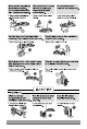
2. Installation of Indoor, Outdoor Unit 1. Selection of the best location 1) Indoor unit Select location Install the air conditioner in the location that satisfies the following conditions. • The place shall easily bear a load exceeding four times the indoor unit’s weight. • The place shall be able to inspect the unit as the figure. • The place where the unit shall be leveled. • The place shall allow easy water drainage.(Suitable dimension “H” is necessary to get a slope to drain as figure.
1. The following should be always observed for safety • Please report to or take consent by the supply authority before connecting to the system. • Be sure to read "THE FOLLOWING SHOULD BE ALWAYS OBSERVED FOR SAFETY" before installing the air conditioner. • Be sure to observe the cautions specified here as they include important items related to safety. • The indications and meanings are as follows. Could lead to serious injury in particular environments when operated incorrectly.
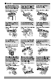
OUT-LINE OF INSTALLATION 1.The following should be always observed for safety............................... 3 Installation works Installation Parts Required tools 2. Installation of Indoor, Outdoor Unit........................................................... 4 • Four Type “A” screws • Level • Screw driver • Connecting cable • Electric drill • Hole core drill (ø70mm) 1) Selection of the best location............................4 2) Indoor unit installation.... 5 3.
CEILING DUCT TYPE AIR CONDITIONERS INSTALLATION INSTRUCTIONS • Please read this instruction sheet completely before installing the product. • When the power cord is wanted to replace, replacement work shall be performed by authorized personnel only. • Installation work must be performed in accordance with national wiring standards by authorized personnel only.