SINGLE-ZONE FOUR-WAY CEILING-CASSETTE SYSTEM ENGINEERING MANUAL Single-Zone Four-Way Ceiling Cassette Heat Pump Systems 3/4 to 3-1/2 Tons LC097HV4 (9,000 Btu/h) LC127HV4 (12,000 Btu/h) LC187HV (18,000 Btu/h) LC247HV (24,000 Btu/h) LC367HV (36,000 Btu/h) LC427HV (42,000 Btu/h)
PROPRIETARY DATA NOTICE This document, as well as all reports, illustrations, data, information, and other materials are the property of LG Electronics U.S.A., Inc., and are disclosed by LG Electronics U.S.A., Inc. only in confidence. This document is for design purposes only. A summary list of safety precautions is on page 4. For more technical materials such as submittals, catalogs, installation, owner’s, and service manuals, visit www.lghvac.com. For continual product development, LG Electronics U.S.
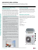
About LG Electronics, Inc. LG Electronics, Inc. is a global leader and technology innovator in consumer electronics, mobile communications, and home appliances. LG Electronics, Inc. comprises five business units— Home Entertainment, Mobile Communications, Air Conditioning, Business Solutions, and Home Appliance. LG is one of the world’s leading producers of flat panel televisions, audio and video products, mobile handsets, air conditioners, and washing machines.
TABLE OF CONTENTS About LG Electronics, Inc............................................................................................................................................................................................... 3 Duct-Free Split (DFS) Systems.......................................................................................................................................................................................
INTRODUCTION “Architectural Appeal” on page 6
ARCHITECTURAL APPEAL Convergence of Technological Innovation with Flexibility and Style Four-Way Ceiling Cassette System Engineering Manual Single-Zone Four-Way CeilingCassette Systems A four-way ceiling-cassette system provides a system designer an edge to engineer a system with many user-adjustable settings.
PRODUCT DATA “Product Features and Benefits” on page 8 “Unit Nomenclature” on page 9 “General Data” on page 10 “Electrical Data” on page 13 “Dimensions” on page 14 “Acoustic Data” on page 20 “Air Velocity and Temperature Distribution” on page 22 “Refrigerant Flow Diagrams” on page 25 “Wiring Diagrams” on page 29 “Accessories” on page 34
PRODUCT FEATURES AND BENEFITS Four-Way Ceiling Cassette System Engineering Manual Four-Way Ceiling Cassette Systems Single zone four-way ceiling cassette systems are equipped with inverter components that offer superior load matching and long piping installation. The product works for optimizing power consumption in residential and small office buildings. Using a four-way ceiling cassette indoor unit with custom temperature controls allow for precise temperature settings in each zone of the building.
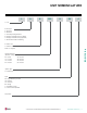
UNIT NOMENCLATURE L A N 090 H SV 4 L = LG Frame Type: A: Art Cool™ S: Standard C: Four-Way Ceiling-Cassette D: Ceiling-Concealed Duct (Low Static) H: Ceiling-Concealed Duct (High Static) V: Vertical-Horizontal Air Handling N: Indoor Unit U: Outdoor Unit No N or U: System Product Data Nominal Capacity (Nominal cooling capacity in Btu/h): 09 = 9,000 30 = 30,000 12 = 12,000 36 = 36,000 18 = 18,000 42 = 42,000 24 = 24,000 54 = 54,000 System Type: H = Heat Pump Style: SV = High Efficiency Inverter V
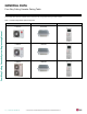
GENERAL DATA Four-Way Ceiling Cassette Pairing Table The following table shows the available outdoor and indoor unit, along with the factory provided controller.
GENERAL DATA / SPECIFICATIONS Single Zone Four-Way Ceiling Cassette LC097HV4 (LCN097HV4 / LUU097HV) LC127HV4 (LCN127HV4 / LUU127HV) PT-QCHW0 / PT-UQC PT-QCHW0 / PT-UQC 3,600 ~ 9,000 ~ 9,900 0.19 ~ 0.66 ~ 0.83 13.65 20.2 4,400 ~ 11,000 ~ 12,100 0.15 ~ 0.83 ~ 1.05 3.88 10.5 3,400 ~ 11,100 ~ 12,400 0.25 ~ 0.88 ~ 1.1 12.6 19.4 2,800 ~ 14,000 ~ 15,500 0.22 ~ 1.19 ~ 1.5 3.44 10.4 7,000 2.92 9,100 2.
Four-Way Ceiling Cassette System Engineering Manual GENERAL DATA / SPECIFICATIONS Table 3: Four-Way Ceiling Cassette System General Data, continued.
ELECTRICAL DATA Electrical Data Table 4: Electrical Data. Nominal Tons Unit Model No. 3/4 1 1-1/2 2 3 3-1/2 LUU097HV LUU127HV LUU187HV LUU247HV LUU367HV LUU427HV Hertz Voltage tolerance is ±10%. Maximum allowable voltage unbalance is 2%. RLA = Rated Load Amps. 60 Voltage 208 - 230 Voltage Range (Min. to Max.) 187 - 253 MCA MOP 11.9 12.3 15 18.1 30 24.5 40 Compressor Quantity Compressor Motor RLA (Cooling) 9.0 1 13.5 18.0 Condenser Fan Motor(s) Condenser Condenser Fan Fan Quantity.
OUTDOOR UNIT DIMENSIONS LUU097HV, LUU127HV Figure 2: LUU097HV, LUU127HV Outdoor Unit Dimensions. 1-3/16 2-9/16 17-11/16 11-11/32 6-5/8 15-11/16 1 2-23/32 13/16 21-15/32 12-31/32 13-29/32 2-3/32 5-21/32 4 - LD.
OUTDOOR UNIT DIMENSIONS LUU187HV, LUU247HV Figure 3: LUU187HV, LUU247HV Outdoor Unit Dimensions. Product Data Due to our policy of continuous product innovation, some specifications may change without notification. ©LG Electronics U.S.A., Inc., Englewood Cliffs, NJ. All rights reserved. “LG” is a registered trademark of LG Corp.
OUTDOOR UNIT DIMENSIONS LUU367HV, LUU427HV Four-Way Ceiling Cassette System Engineering Manual Figure 4: LUU367HV, LUU427HV Outdoor Unit Dimensions. 16 | FOUR-WAY CASSETTE Due to our policy of continuous product innovation, some specifications may change without notification. ©LG Electronics U.S.A., Inc., Englewood Cliffs, NJ. All rights reserved. “LG” is a registered trademark of LG Corp.
INDOOR UNIT DIMENSIONS LCN097HV4, LCN127HV4 Figure 5: LCN097HV4, LCN127HV4 Indoor Unit Dimensions. Product Data Due to our policy of continuous product innovation, some specifications may change without notification. ©LG Electronics U.S.A., Inc., Englewood Cliffs, NJ. All rights reserved. “LG” is a registered trademark of LG Corp.
INDOOR UNIT DIMENSIONS LCN187HV, LCN247HV Job Name/Location: Indoor Unit (IDU) ‐ LCN187HV Ceiling Cassette Single Zone Date: PO No.: Four-Way Ceiling Cassette System Engineering Manual Figure 6: LCN187HV, LCN247HV Indoor Unit Dimensions. Tag #: 18 For continual product development, LG reserves the right to change specifications without notice. © Electronics U.S.A., Inc., Englewood Cliffs, NJ. All rights reserved. “LGpolicy Life’s of Good” is a registered trademarksome of LGspecifications Corp. /www.
INDOOR UNIT DIMENSIONS LCN367HV, LCN427HV Job Name/Location: Indoor Unit (IDU) ‐ LCN367HV Ceiling Cassette Single Zone Figure 7: LCN367HV, LCN427HV Indoor Unit Dimensions. Tag #: Date: PO No.: Product Data For continual product development, LG reserves the right to change specifications without notice. © LG Electronics U.S.A., Inc., Englewood Cliffs, NJ. All rights reserved. “LG Life’s Good” is a registered trademark of LG Corp. /www.lghvac.
ACOUSTIC DATA Outdoor Units Figure 8: Four-Way Ceiling Cassette Outdoor Unit Sound Pressure Level Measurement Location. Table 5: Four-Way Ceiling Cassette Outdoor Unit Sound Pressure Levels (dB[A]). Sound Pressure Levels (dB[A]) Model Cooling Heating NC-60 NC-55 NC-50 NC-45 NC-40 NC-35 NC-30 NC-25 D 3.3 ft. Figure 9: Four-Way Ceiling Cassette Outdoor Unit Sound Pressure Level Diagrams.
ACOUSTIC DATA Indoor Units Figure 10: Indoor Unit Sound Pressure Level Measurement Location. • Measurements taken with no attenuation and units operating at full load normal operating condition. • Sound level will vary depending on a range of factors such as construction (acoustic absorption coefficient) of particular area in which the equipment is installed. • Sound power levels are measured in dB(A)±3. • Tested in anechoic chamber per ISO Standard 3745.
AIR VELOCITY AND TEMPERATURE DISTRIBUTION Figure 12: LCN097HV4 Air Velocity and Temperature Distribution Charts. Cooling Discharge angle: 40° Heating Discharge angle: 50° Air velocity [ft/s] Air velocity [ft/s] 9ft Four-Way Ceiling Cassette System Engineering Manual 6.6 6.6 4.9 6.6 4.9 7ft 4.9 3.3 3.3 3.3 1.6 8ft 7ft 3.3 1.6 3ft 9ft 6.6 4.9 1.6 3ft 1.
AIR VELOCITY AND TEMPERATURE DISTRIBUTION Figure 14: LCN187HV Air Velocity and Temperature Distribution Charts. Cooling Heating Discharge angle: 40° Discharge angle: 50° Air velocity [ft/s] Air velocity [ft/s] 9ft 6.6 6.6 9ft 7ft 7ft 6.6 4.6 3.3 3.3 13ft 10ft 7ft 3ft 4.6 3ft 0ft 3ft 7ft 10ft 0ft 13ft 10ft 7ft 3ft 9ft 64 68 72 0ft 3ft 7ft 10ft 0ft 13ft 73 7ft 73 3ft 0ft 3ft 72 75 75 7ft 10ft 13ft 13ft 10ft 7ft 9ft 91 91 86 7ft 3ft 75 1.6 1.
AIR VELOCITY AND TEMPERATURE DISTRIBUTION Figure 16: LCN367HV Air Velocity and Temperature Distribution Charts. Cooling Heating Discharge angle: 40° Discharge angle: 50° Air velocity [ft/s] Air velocity [ft/s] 10.5ft Four-Way Ceiling Cassette System Engineering Manual 13.1 13.1 13.1 9.8 9.8 9.8 7ft 9.8 10.5ft 13.1 7ft 3ft 3ft 16ft 13ft 10ft 6.6 6.6 3.3 6.6 3.3 7ft 3ft 0ft 3ft 7ft 10ft 13ft 0ft 16ft 3.3 16ft 13ft 68 7ft 68 72 10ft 3.
OUTDOOR UNIT REFRIGERANT FLOW DIAGRAM LUU097, 127HV Figure 18: LUU097, 127HV Refrigerant Flow Diagram.
INDOOR UNIT REFRIGERANT FLOW DIAGRAM LCN097, 127HV4 Figure 19: LCN097, 127HV4 Refrigerant Flow Diagram. Gas pipe connection port (flare connection) Heat exchanger Four-Way Ceiling Cassette System Engineering Manual Heating Cooling Evaporator Outlet Temperature Thermistor Turbo fan M Indoor Air Temperature Thermistor Evaporator Inlet Temperature Thermistor Liquid pipe connection port (flare connection) Table 8: Four-Way Ceiling Cassette Indoor Unit Refrigerant Pipe Connection Port Diameters.
OUTDOOR UNIT REFRIGERANT FLOW DIAGRAM LUU187, 247, 367, 427HV Figure 20: LUU187, 247, 367, 427HV Refrigerant Flow Diagram.
INDOOR UNIT REFRIGERANT FLOW DIAGRAM LCN187, 247, 367, 427HV Figure 21: LCN187, 247, 367, 427HV Refrigerant Flow Diagram.
OUTDOOR UNIT WIRING DIAGRAM LUU097HV and LUU127HV Figure 22: Four-Way Ceiling Cassette LUU097HV and LUU127HV Outdoor Unit Wiring Diagram. Product Data Due to our policy of continuous product innovation, some specifications may change without notification. ©LG Electronics U.S.A., Inc., Englewood Cliffs, NJ. All rights reserved. “LG” is a registered trademark of LG Corp.
OUTDOOR UNIT WIRING DIAGRAM LUU187HV and LUU247HV Four-Way Ceiling Cassette System Engineering Manual Figure 23: Four-Way Ceiling Cassette LUU187HV and LUU247HV Outdoor Unit Wiring Diagram. 30 | FOUR-WAY CASSETTE Due to our policy of continuous product innovation, some specifications may change without notification. ©LG Electronics U.S.A., Inc., Englewood Cliffs, NJ. All rights reserved. “LG” is a registered trademark of LG Corp.
OUTDOOR UNIT WIRING DIAGRAM LUU367HV and LUU427HV Figure 24: Four-Way Ceiling Cassette LUU367HV and LUU427HV Outdoor Unit Wiring Diagram. Product Data Due to our policy of continuous product innovation, some specifications may change without notification. ©LG Electronics U.S.A., Inc., Englewood Cliffs, NJ. All rights reserved. “LG” is a registered trademark of LG Corp.
INDOOR UNIT WIRING DIAGRAM LCN097,127HV4 Four-Way Ceiling Cassette System Engineering Manual Figure 25: Four-Way Ceiling Cassette LCN097, 127HV4 Indoor Unit Wiring Diagram. 32 | FOUR-WAY CASSETTE Due to our policy of continuous product innovation, some specifications may change without notification. ©LG Electronics U.S.A., Inc., Englewood Cliffs, NJ. All rights reserved. “LG” is a registered trademark of LG Corp.
INDOOR UNIT WIRING DIAGRAM LCN187, 247, 367, 427HV Figure 26: Four-Way Ceiling Cassette LCN187, 247, 367, 427 HV Indoor Unit Wiring Diagram. Product Data Due to our policy of continuous product innovation, some specifications may change without notification. ©LG Electronics U.S.A., Inc., Englewood Cliffs, NJ. All rights reserved. “LG” is a registered trademark of LG Corp.
ACCESSORIES Functions, Controls, and Options Table 13: Indoor Units—Functions, Controls and Options. Operation Controllers Four-Way Ceiling Cassette System Engineering Manual Airflow Indoor Unit Type 1 2 Four-Way Ceiling-Cassette Air supply outlets Airflow direction control (up & down) Auto swing (up and down) Airflow steps (fan/cool/heat) Chaos wind (auto wind) Jet cool/heat Swirl wind Plasma air purifier Washable anti-fungal1 Drain pump E.S.P.
ACCESSORIES LGMV Diagnostic Software LG Monitoring View (LGMV) Diagnostic Software and Cable LGMV software allows the service technician or commissioning agent to connect a computer USB port to the outdoor unit main printed circuit board (PCB) using an accessory cable without the need for a separate interface device.
PERFORMANCE DATA “Cooling Capacity Data” on page 37 “Heating Capacity Data” on page 43
PERFORMANCE DATA Cooling Capacity Tables Table 15: LC097HV4 System Cooling Capacity Table. Model No. / Outdoor Nominal Capacity Air Temp. (Btu/h) (°F DB) -4 LC097HV4 / 9,000 68 / 57 TC SHC 8.85 6.84 PI 73 / 61 TC SHC 0.39 9.40 7.23 PI Indoor Air Temp. °F DB / °F WB 77 / 64 80 / 67 TC SHC PI TC SHC PI 86 / 72 TC SHC 0.40 9.95 11.05 7.00 0.42 10.34 7.15 0.42 7.21 PI 0.43 90 / 75 TC SHC 11.60 7.34 PI 0.44 0 8.84 6.88 0.39 9.39 7.27 0.41 9.94 7.04 0.42 10.34 7.19 0.43 11.
PERFORMANCE DATA Cooling Capacity Tables Table 16: LC127HV4 System Cooling Capacity Table. Model No. / Outdoor Nominal Capacity Air Temp. (Btu/h) (°F DB) Four-Way Ceiling Cassette System Engineering Manual -4 LC127HV4 / 12,000 68 / 57 TC SHC 10.91 7.83 PI 73 / 61 TC SHC PI 0.52 11.59 0.54 8.27 Indoor Air Temp. °F DB / °F WB 77 / 64 80 / 67 TC SHC PI TC SHC PI 12.27 0.56 12.76 8.17 0.57 13.62 8.24 PI 0.58 90 / 75 TC SHC 14.30 8.40 PI 0.59 0 10.91 7.87 0.53 11.58 8.32 0.55 12.
PERFORMANCE DATA Cooling Capacity Tables Table 17: LC187HV System Cooling Capacity Table. Model No. / Outdoor Nominal Capacity Air Temp. (Btu/h) (°F DB) 5 LC187HV / 18,000 TC 68 / 57 SHC PI TC 73 / 61 SHC PI 17.83 14.43 0.50 18.94 15.24 0.68 Indoor Air Temp. °F DB / °F WB 77 / 64 80 / 67 TC SHC PI TC SHC PI 20.04 15.69 0.74 20.84 15.07 0.75 TC 86 / 72 SHC PI TC 90 / 75 SHC PI 22.26 15.19 0.75 23.37 15.48 0.75 10 17.80 14.53 0.52 18.91 15.35 0.70 20.02 15.80 0.
PERFORMANCE DATA Cooling Capacity Tables Table 18: LC247HV System Cooling Capacity Table. Model No. / Outdoor Nominal Capacity Air Temp. (Btu/h) (°F DB) Four-Way Ceiling Cassette System Engineering Manual 5 LC247HV / 24,000 TC 68 / 57 SHC PI TC 73 / 61 SHC PI 23.77 17.54 0.76 25.25 18.53 1.03 Indoor Air Temp. °F DB / °F WB 77 / 64 80 / 67 TC SHC PI TC SHC PI 26.73 1.12 27.79 18.32 1.13 86 / 72 SHC PI TC 90 / 75 SHC PI 29.68 18.47 1.14 31.15 18.82 1.13 10 23.74 17.67 0.
PERFORMANCE DATA Cooling Capacity Tables Table 19: LC367HV System Cooling Capacity Table. Model No. / Outdoor Nominal Capacity Air Temp. (Btu/h) (°F DB) 5 LC367HV / 36,000 68 / 57 TC SHC PI 1.18 73 / 61 TC SHC 37.87 27.18 PI 1.60 Indoor Air Temp. °F DB / °F WB 77 / 64 80 / 67 TC SHC PI TC SHC PI 40.09 27.98 1.74 41.69 26.87 1.76 TC 44.52 86 / 72 SHC 27.10 PI 1.77 TC 46.73 90 / 75 SHC 27.61 PI 35.66 25.73 1.76 10 35.61 25.92 1.22 37.82 27.38 1.65 40.03 28.18 1.79 41.
PERFORMANCE DATA Cooling Capacity Tables Table 20: LC427HV System Cooling Capacity Table. Model No. / Outdoor Nominal Capacity Air Temp. (Btu/h) (°F DB) Four-Way Ceiling Cassette System Engineering Manual 5 LC427HV / 42,000 68 / 57 TC SHC 41.60 30.30 PI 1.62 73 / 61 TC SHC 44.19 32.00 PI 2.20 Indoor Air Temp. °F DB / °F WB 77 / 64 80 / 67 TC SHC PI TC SHC PI 46.77 2.38 48.64 31.64 2.42 51.94 86 / 72 SHC 31.91 PI 2.42 TC 54.52 90 / 75 SHC 32.51 PI 2.42 10 41.54 30.52 1.
PERFORMANCE DATA Heating Capacity Tables Table 21: LC097HV4 System Heating Capacity Table. Model No. / Nominal Capacity (Btu/h) LC097HV4 / 9,000 Outdoor Air Temp. °F DB °F WB -4 0 5 10 17 20 25 30 35 40 45 47 50 55 60 63 68 -4.4 -0.4 4.5 9 15 19 23 28 32 36 41 43 46 51 56 59 64 TC 61 4.38 5.22 6.22 6.89 7.63 8.07 8.82 9.57 10.33 10.85 11.51 11.77 11.81 11.87 11.92 11.96 11.99 PI 0.61 0.62 0.63 0.63 0.65 0.66 0.67 0.69 0.71 0.73 0.75 0.77 0.76 0.75 0.74 0.74 0.73 TC 64 4.06 4.91 5.93 6.61 7.
PERFORMANCE DATA Heating Capacity Tables Table 23: LC187HV System Heating Capacity Table. Four-Way Ceiling Cassette System Engineering Manual Model No. / Nominal Capacity (Btu/h) LC187HV / 18,000 Outdoor Air Temp. °F DB °F WB 0 5 10 17 20 25 30 35 40 45 47 50 55 60 63 68 -0.4 4.5 9 15 19 23 28 32 36 41 43 46 51 56 59 64 TC 61 8.96 10.89 12.18 13.60 14.46 15.90 17.34 18.78 19.73 20.93 21.41 21.47 21.58 21.68 21.74 21.81 PI 1.12 1.14 1.15 1.17 1.19 1.22 1.25 1.28 1.32 1.36 1.38 1.37 1.36 1.35 1.
PERFORMANCE DATA Heating Capacity Tables Table 25: LC367HV System Heating Capacity Table. Model No. / Nominal Capacity (Btu/h) LC367HV / 36,000 Outdoor Air Temp. °F DB °F WB 0 5 10 17 20 25 30 35 40 45 47 50 55 60 63 68 -0.4 4.5 9 15 19 23 28 32 36 41 43 46 51 56 59 64 TC 61 19.98 23.43 25.75 28.29 29.83 32.40 34.98 37.55 39.47 41.86 42.82 42.94 43.15 43.36 43.49 43.61 PI 2.41 2.44 2.47 2.51 2.54 2.60 2.67 2.73 2.81 2.91 2.95 2.93 2.90 2.87 2.85 2.83 TC 64 18.81 22.34 24.71 27.31 28.88 31.
Four-Way Ceiling Cassette System Engineering Manual 46 | FOUR-WAY CASSETTE Due to our policy of continuous product innovation, some specifications may change without notification. ©LG Electronics U.S.A., Inc., Englewood Cliffs, NJ. All rights reserved. “LG” is a registered trademark of LG Corp.
APPLICATION GUIDELINES “Equipment Selection Procedure” on page 48 “Building Ventilation Design Guide” on page 50 “Placement Considerations” on page 55
EQUIPMENT SELECTION PROCEDURE Cooling / Heating Correction Factors For Four-Way Ceiling Cassette systems, calculate the equivalent length of the liquid line from the outdoor unit to the indoor unit. Also, determine the elevation difference of the indoor unit above or below the outdoor unit. Find corresponding cooling or heating capacity correction factors as shown below. Multiply the correction factors by the cooling or heating capacity obtained from the capacity table using design conditions.
EQUIPMENT SELECTION PROCEDURE Defrost Correction Factor for Heating Operation The outdoor unit heating capacity may need to be adjusted for frost accumulation on air-cooled systems. If design day conditions are below the dewpoint of the surrounding air, frost may not be a problem and no correction factor is needed. In certain weather conditions, however, frost may form and accumulate on the air-cooled outdoor unit coil and impact the coils ability to transfer heat.
BUILDING VENTILATION DESIGN GUIDE ASHRAE Standards 62.1 and 62.2 (depending on if the building is residential or commercial), and local codes specify the minimum volume of airflow that must be provided to an occupied space. Outdoor air is required to minimize adverse health effects, and it provides acceptable indoor air quality for building occupants. Indoor units located within the zone typically require less airflow to condition the space.
BUILDING VENTILATION DESIGN GUIDE Method 2: Unconditioned Outdoor Air (Non-Ducted, Fan Assisted Ventilation) When approved by local codes, the fan assisted ventilation method uses exhaust fans to remove air from the building, and outdoor air is drawn into occupied spaces through a wall louver or gravity roof intake hood. Supply fans can also be used to push the outdoor air into the space and building positive pressure will vent the exhaust air through louvers or roof-mounted exhaust hoods.
BUILDING VENTILATION DESIGN GUIDE Method 3: Unconditioned Outdoor Air Ducted to Indoor Units Four-Way Ceiling Cassette System Engineering Manual Untreated outdoor air is channeled through a duct system that is piped to the return air duct on Duct-Free Split system ducted indoor units or to the frame of Duct-Free Split system four-way cassettes. Outside air may flow backward through the return air-filter grille when the indoor unit fan speed slows or stops in response to changes in the space load.
BUILDING VENTILATION DESIGN GUIDE Method 4: Coupled Dedicated Outdoor Air (CDOA) A separate, dedicated outdoor air system delivers air directly to a Duct-Free Split system indoor unit or to the return air duct system. After mixing with the return air stream, ventilation air passes through the indoor unit and into the conditioned space. The pretreatment system is capable of filtering, conditioning, and dehumidifying outdoor air to room neutral conditions.
BUILDING VENTILATION DESIGN GUIDE Method 5: Decoupled Dedicated Outdoor Air System (DDOAS) LG recommends using the DDOAS method in all installations. Advantages • May be used with the full lineup of Duct-Free Split system indoor units. • The outdoor air unit may supply “neutral” air to the occupant space even when the Duct-Free Split system indoor unit fan changes speed or cycles on and off. DDOAS controls do not have to be interlocked with the Duct-Free Split system.
PLACEMENT CONSIDERATIONS Indoor Unit Selecting the Best Location for the Indoor Unit The unit should not be installed where sulfuric acid and flammable or corrosive gases are generated, vented into, or stored. There is risk of fire, explosion, and physical injury or death. Don’ts • No obstacles to air circulation around the unit; keep proper distances from ceilings, doorways, floor, walls, etc.
PLACEMENT CONSIDERATIONS Indoor Unit Installing in an Area Exposed to Unconditioned Air Installing in an Area with High Humidity Levels If the environment is prone to humidity levels of 80% or more (near the ocean, lakes, etc.) or where steam could collect in the plenum: • Install additional insulation to the indoor unit (glass wool insulation >13/32 inches thick). • Install additional insulation to the refrigerant piping (insulation >13/16 inches thick).
PLACEMENT CONSIDERATIONS Outdoor Unit Selecting the Best Location for the Outdoor Unit DANGER To avoid the possibility of fire, do not install the unit in an area where combustible gas may generate, flow, stagnate, or leak. Failure to do so will cause serious bodily injury or death. Install a fence to prevent vermin from crawling into the unit or unauthorized individuals from accessing it.
PLACEMENT CONSIDERATIONS Outdoor Unit Four-Way Ceiling Cassette System Engineering Manual Tie-Downs / Wind Restraints and Lightening Protection The strength of the Four-Way Ceiling Cassette system outdoor unit frame is adequate to be used with field-provided wind restraint tie-downs. Tie-Downs / Wind Restraints • The strength of the roof must be checked before installing the outdoor units.
PLACEMENT CONSIDERATIONS Outdoor Unit Bolting the Outdoor Unit to the Platform Figure 38: Bolting the LUU097HV and LUU127HV Outdoor Units to the Platform (Appearance May Vary). Figure 39: Bolting the LUU187HV and LUU247HV Outdoor Unit to the Platform.
PLACEMENT CONSIDERATIONS Outdoor Unit Four-Way Ceiling Cassette System Engineering Manual Minimum Allowable Clearance and Service Access Requirements Proper clearance for the outdoor unit coil is critical for proper unit operation. When installing the outdoor unit, consider service, inlet and outlet and minimum allowable space requirements as illustrated in the diagrams on the following pages. • Include enough space for airflow and for service access.
PLACEMENT CONSIDERATIONS Outdoor Unit Outdoor Unit (36,000 and 42,000 Btu/h Capacity) Service Access and Allowable Clearances When installing the outdoor unit, consider service, inlet, and outlet, and minimum allowable space requirements as illustrated in the following diagrams.
PLACEMENT CONSIDERATIONS Outdoor Unit are obstacles on both suction Obstacles andthere on the Obstacles above and on above the Where and discharge sides (discharge side obstacle air discharge side. air discharge side. is higher than" the outdoor unit).
REFRIGERANT PIPING DESIGN & LAYOUT BEST PRACTICES “Refrigerant Piping Design” on page 64 "Selecting Field-Supplied Copper Tubing" on page 65 "Refrigerant Piping System Layout" on page 66 "Electrical Connections" on page 73
REFRIGERANT PIPING DESIGN Design Guideline Summary Device Connection Limitations A single-zone four-way ceiling cassette system consists of one outdoor unit and one indoor unit. One of the most critical elements of a single-zone four-way ceiling cassette system is the refrigerant piping. The table below lists pipe length limits that must be followed in the design of a single-zone four-way ceiling cassette refrigerant pipe system.
REFRIGERANT PIPING DESIGN Selecting Field-Supplied Copper Tubing Figure 47: Coiled Expansion Loops and Offsets. L L L L L L R R R L L L R R R Large Tubing U-bend (>3/4 in.) Small Tubing U-bend (<3/4 in.) Loop Anticipated Linear Expansion (LE) (inches) R1 L2 R1 L2 R1 L2 R1 L2 R1 L2 R1 L2 R1 L2 R1 L2 1/2 1 1-1/2 2 2-1/2 3 3-1/2 4 1 2 R = Centerline Length of Pipe. L = Centerline Minimum Radius (inches).
REFRIGERANT PIPING DESIGN Selecting Field-Supplied Copper Tubing / Refrigerant Piping System Layout Definitions Physical Pipe Length: Actual length of straight segment(s) of pipe. Equivalent Pipe Length: Actual length of pipe plus equivalent lengths of long radius elbows, Y-branches, and valves. Four-Way Ceiling Cassette System Engineering Manual Layout Procedure 1. Draft a one-line diagram of the proposed piping system connecting outdoor unit to indoor units.
INSTALLATION & LAYOUT BEST PRACTICES Refrigerant Piping System Layout No Pipe Size Substitutions Using a different size is prohibited and may result in a system malfunction or failure to work at all. Figure 49: Installing an Insert Into a Concrete Beam. Inserts and Pipe Supports Inserts Insert Anti-vibration Material A properly installed pipe system should be adequately supported to avoid pipe sagging. Sagging pipes become oil traps that lead to equipment malfunction.
INSTALLATION & LAYOUT BEST PRACTICES Refrigerant Piping System Layout Pipe Sleeves at Penetrations LG requires that all pipe penetrations through walls, floors, and pipes buried underground be properly insulated and routed through an appropriate wall sleeve of sufficient size to prevent compression of refrigerant pipe insulation and free movement of the pipe within the sleeve. Underground refrigerant pipe shall be routed inside a protective sleeve to prevent insulation deterioration.
INSTALLATION & LAYOUT BEST PRACTICES Refrigerant Piping System Layout Single Zone Cassette Outdoor Unit Connections 1. Remove the connection cover from the unit by loosening the screws. 2. Align the center of the refrigerant pipe and corresponding connection. 3. Place a couple of drops of refrigerant oil on the opening rim of the flare before assembling. Ensure you do not add any contaminants. Tighten the flare nut initially by hand. 4.
INSTALLATION & LAYOUT BEST PRACTICES Refrigerant Piping System Layout Brazing Practices Four-Way Ceiling Cassette System Engineering Manual It is imperative to keep the piping system free of contaminants and debris such as copper burrs, slag, or carbon dust during installation. All joints are brazed in the field. Single Zone Cassette refrigeration system Figure 59: Refrigerant Pipe Brazing.
INSTALLATION & LAYOUT BEST PRACTICES Refrigerant Piping System Layout Refrigerant Piping System Insulation All refrigerant piping including connections, field-provided isolation ball valves, service valves, and elbows shall be completely insulated using closed cell pipe insulation. The design engineer should perform calculations to determine if the factory-supplied insulation jackets are sufficient to meet local codes and avoid sweating.
CONDENSATE DRAIN PIPING Condensate Drain Piping Condensate drain piping should be constructed out of materials approved by local codes (generally PVC). Drain piping must have downward gradient of at least 1/50 to 1/100; to prevent reverse flow, slope should not be straight up and down, and support hangers should be used at 3-5/16 to 5 foot intervals to keep the condensate drainage system stable.
ELECTRICAL CONNECTIONS Outdoor Unit Power Wiring / Communications Cable Connections LUU097HV, LUU127HV, LUU187HV, LUU247HV Outdoor Unit Connections Figure 63: LUU097, 127HV Outdoor Unit Terminal Block Location. 1. Remove the cover from the unit by loosening the fastening screws. 2. Take off the caps on the conduit panel. 3. Connect both the power supply and low voltage lines to the corresponding terminals on the terminal block. 4. Be sure to ground the unit by following local codes. 5.
ELECTRICAL CONNECTIONS Four-Way Ceiling Cassette System Engineering Manual Cassette Indoor Unit Power Wiring / Communications Cable Connections Figure 67: Power Wiring and Communications Cable Connection Access. 1. To access the terminal block, open the control box cover. 2. Insert the power wiring / communications cable from the outdoor unit through the sides of the indoor unit and control box. Pass the wiring through the designated access holes to prevent damage.
ELECTRICAL CONNECTIONS Figure 69: Detailed Power / Communications System Schematic.
TECHNICAL DATA “Mechanical Specifications” on page 77 “Acronyms” on page 79
MECHANICAL SPECIFICATIONS Four-Way Ceiling Cassette System General System Outdoor Unit The outdoor units have sound levels not exceeding 54 dB(A) tested in an anechoic chamber under ISO Standard 3745. Indoor Unit The indoor units have sound ratings no higher than 46 dB(A) as tested per ISO Standard 3745. Temperature Ranges Figure 70: Four-Way Ceiling Cassette System (LC187HV, LC247HV Models).
MECHANICAL SPECIFICATIONS Four-Way Ceiling Cassette System Coil Four-Way Ceiling Cassette System Engineering Manual Outdoor Unit Heat pump outdoor unit coils are made of nonferrous louvered aluminum fins protected with an integral coil guard. The coil for each outdoor unit has a minimum of 14 fins per inch (FPI); heat exchanger has two rows.
ACRONYMS Table 46: Table of Acronyms.
20001747 ISO 9001: 2008 LG ELECTRONICS INC. LG Electronics, U.S.A., Inc. Commercial Air Conditioning Division 4300 North Point Parkway Alpharetta, Georgia 30022 www.lg-dfs.com LG Electronics Commercial Products Support 1-888-865-3026 USA Follow the prompts for commercial A/C products.