
Installing DFS Outdoor Units in Winter Conditions

• Consider tie-down requirements in case of high winds, wall, rooftop installations, or where required by local codes (area must be
checked for stability and strength before installation).
• The frames of LG outdoor units are adequate to be used with field-provided wind restraint tie-downs.
• Securely anchor the mounting base using a field-provided tie-down configuration approved by a local professional engineer.
• Verify the outdoor unit is level, and adheres to all clearance requirements.
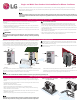
M10
Anchor Bolt
2-3/4~4-23/32
13/16
Unit: Inch
Close Up of an Installed Bolt
Outdoor Unit Mounting Recommendations, Continued
Bolt
Refrigerant Pipe
Connection
Top of Outdoor Unit
(Looking Down)
Mounting Base &
Anti-Vibration
Pad
Bolt
Bolt
Bolt
Outdoor Unit Mounted to an H-Beam
on a Concrete Slab
Outdoor Unit Mounted to a Platform
Bolting the Outdoor Unit to the Mounting Base
Bolting the Outdoor Unit to the Mounting Base
• In climates that may experience significant snow buildup, place the outdoor unit on a raised, field-provided platform or stand to ensure
proper outdoor unit coil airflow. The raised support platform must be high enough to allow the unit to remain above possible snow
drifts, and is higher than the maximum anticipated snowfall for the location
• Best practice prevents snow from accumulating on top of the unit. Clean off the top of the outdoor unit if the snow has accumulated
4 inches or more.
• Design the mounting base to prevent snow accumulation on the platform in front or back of the unit frame.
• If necessary, provide a field-fabricated hood to keep snow and ice and / or drifting snow from accumulating on the coil surfaces.
• Use inlet and discharge duct or hoods to prevent snow from accumulating on the outdoor unit fan inlet and outlet guards.
• Install the outdoor unit air inlet and discharge areas away from prevailing winter winds.
If snow accumulates and freezes on the air inlet, the system may malfunction.
Planning for Snow and Ice
• Outdoor units require condensate drain piping.
• Depending on the complexity of the system, indoor units may drain condensate directly outside, or individual indoor unit drain pipes
may need to be connected to one common, dedicated indoor unit drainage system that would carry all condensate outside. If the
indoor unit drainage system is shared with a rainwater drain, waste water, or any other type of building drain system, back flow, leaks,
ice may form, or noxious odors may be present.
• Design all drain systems to plan for winter operation (line[s] may freeze if condensate does not properly drain away).
• Install condensate drain pipes constructed with materials approved by local code.
• To prevent condensate from forming on the outdoor unit drain piping, install a minimum of field-supplied 0.4 inch thick polyethylene.
The insulation should be securely fastened with all seams tight and connected joints and ends properly covered.
When deciding on a location to place the
outdoor unit or the end of the indoor unit
condensate drain line, choose an area where
run-off from defrost will not accumulate
and freeze on sidewalks or driveways, which
may create unsafe conditions.
CAUTION
• All refrigerant piping — including connections, service valves, and elbows — should be completely and correctly insulated with
closed cell pipe insulation.
• To prevent heat loss / heat gain through the refrigerant piping, all refrigerant piping including liquid lines and vapor lines
should be insulated separately. Insulation should be a minimum of 1/2 inch thick; thickness may need to be increased based
on ambient conditions and local codes.
• All insulation joints should be glued tight with no air gaps. Insulation material must fit snugly against the refrigeration pipes
with no air space between it and the pipes.
• The design engineer should perform calculations to determine if the factory-supplied insulation jackets are sufficient to meet
local codes and avoid sweating. Additional insulation can be installed if necessary.
• All pipe insulation exposed to outdoor elements should be properly protected with PVC, aluminum vapor barrier, conduit, wide
vinyl tape, or alternatively placed in a weather-resistant enclosure such as a pipe rack with a top cover; and meet local codes.
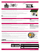
Typical Piping, Insulation, Power Wire and
Communications Cable Arrangement in a Conduit
Vapor Line
Liquid Line
Cable
Power/Communication
Pi
p
e Sleeve
Insulation Material
Insulation
Material
Properly insulate all cold surfaces to prevent “sweating.”
Cold surfaces such as uninsulated piping can generate condensate that could drip and freeze in cold weather, causing a slippery surface that creates a risk of slipping, falling, and personal injury.
TT-WinterConditionInstallation _DFS_2_16
Tie-Downs and Wind Restraints
Condensate Drain Piping
Refrigerant Piping System Insulation
For more detailed installation and specification information, see the Engineering and Installation Manuals specific to the chosen system. If it is possible
to install the outdoor unit in an indoor environment, see the Engineering Manual specific to the chosen system for information.
Sunroof
Always refer to local code when rooftop
mounting requirements and / or designing
a wind restraint system.
Wind Baffles for Low Ambient Cooling Applications.
Model No. For Use With
ZLABGP01A 9,000 and 12,000 Btu Single Zone ODUs
ZLABGP02A 18,000 to 36,000 Btu Single Zone ODUs
ZLABGP03A 18,000 and 24,000 Btu Multi Zone ODUs
ZLABGP04A
18,000 to 60,000 Btu large frame Single Zone and Multi Zone ODUs
(some models require two wind baffles)
Accessories for Winter / Cold Weather Conditions
Drain Pan Heater
Model No. For Use With
PQSH1200 All Multi F Outdoor Units
PQSH1201
LSU180HSV4 and
LAU240HSV3
LG offers some outdoor unit accessories
for use in winter / cold weather conditions.
For more information, see www.lg-dfs.com.